You measure both ends of a ten-foot bend—each reads a flawless 90 degrees. Then you check the center, and it opens up to 92. Naturally, you suspect inconsistent steel or a worn die. But the real issue isn’t the material at all—it’s your machine physically flexing under pressure. This phenomenon, known as the “Canoe Effect,” occurs when the press brake itself bends under forming loads, producing parts that are tight at the ends and open in the middle, just like the shape of a canoe.
Understanding this effect is key when choosing the right Press Brake Toolings or upgrading your existing setup for better accuracy.
To grasp why your parts curve like canoes, you need to stop thinking of the press brake as a perfectly rigid structure. Under the immense forces of bending, even cast iron and steel behave elastically—they flex like very stiff springs.
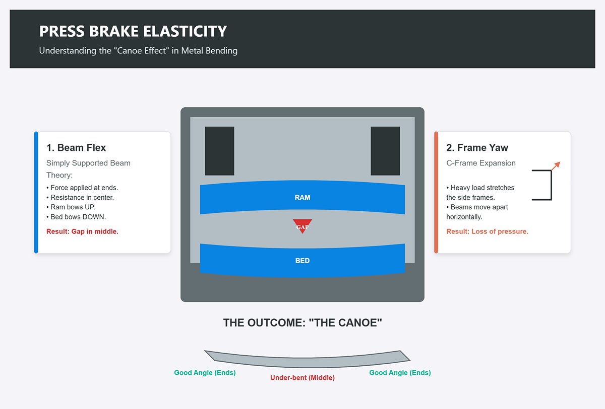
When the hydraulic cylinders at each end push the ram downward against the workpiece, the system behaves much like a simply supported beam. The pressure is applied at the ends, while the resistance spreads along the entire length. As a result, two types of deformation occur at once:
The result is a press brake that appears to “smile” at you. The ram and bed remain tightly aligned near the ends—where hydraulic pressure acts most directly—producing correct bends there. But in the center, where the material is least supported, the beams drift apart, leaving the bend angle open.
For consistent accuracy, pairing your machine with Press Brake Crowning solutions or precision-engineered Amada Press Brake Tooling can drastically reduce these deviations.
Deflection does not occur in a straight line; it follows a parabolic curve. If you were to chart the reduction in penetration depth along a 10-foot press brake, you wouldn’t see a simple linear gradient from the ends to the center. Instead, the graph would arch—showing that the loss of accuracy accelerates as you move away from the side frames.
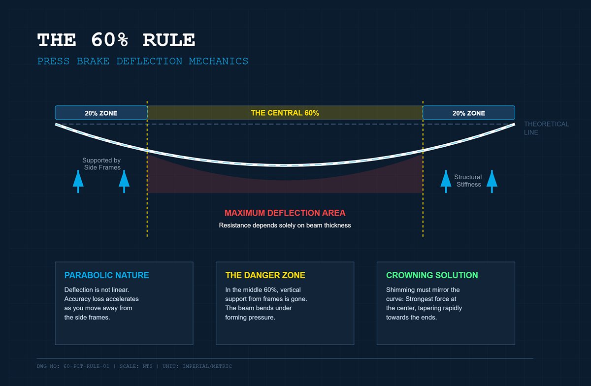
According to the “60% Rule” in deflection mechanics, most of the deviation from the intended angle happens within the central 60% of the span between the side frames. The outer 20% sections near each cylinder—the left and right ends—benefit from the structural stiffness of the side columns, which effectively counteract bending.
However, once you move beyond these reinforced edge zones, the resistance to bending drops sharply. In this central “danger zone,” the structure’s ability to oppose the forming pressure depends solely on the cross-sectional depth and thickness of the beams, rather than the vertical support of the frames.
This concentration of flex explains why shimming is rarely straightforward. You cannot simply insert shims of equal thickness across the midsection. To offset the parabolic pattern of deflection, crowning systems—whether manual or CNC-controlled—must apply compensating force that mirrors the curve: strongest at the center and tapering rapidly toward the more rigid 20% zones at either end.
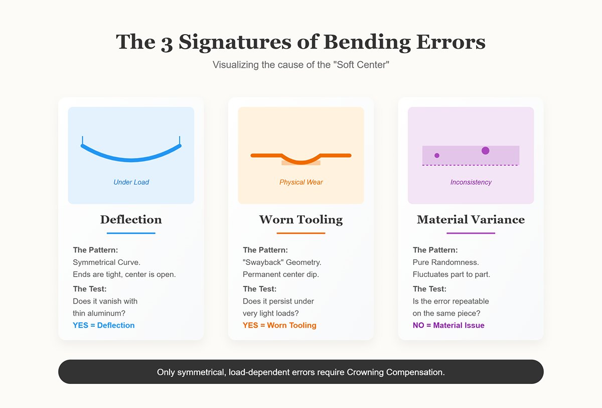
Before installing a crowning system or beginning any die shimming, you need to confirm that deflection is actually the cause. A “soft center” can stem from three distinct issues: machine deflection, worn tooling, or material inconsistency.
To identify deflection, examine whether the error pattern remains consistent throughout production.
The Deflection Signature: When the angular deviation is symmetrical—both ends reading identically (e.g., 90°) while the center consistently measures open (e.g., 92°)—and this pattern repeats across multiple pieces from the same batch, you’re dealing with machine deflection. The effect becomes more pronounced as tonnage increases (thicker materials or tighter V-die openings) and diminishes with lighter-gauge work. If the problem vanishes when bending thin aluminum, the issue is almost certainly deflection tied to load intensity.
The Worn Tooling Signature: Tool wear almost never occurs evenly. If your die shows a “swayback” shape—worn down in the center from years of forming short parts on the middle of the bed—you’ll see bending errors even under light loads. Examine the die radius carefully: if there’s noticeable grooving or wear in the center but not on the ends, the “canoe effect” you’re seeing stems from worn tooling geometry rather than from machine deflection.
The Material Variance Signature: When your bend angles fluctuate unpredictably—tight in the middle on one part, open on the next, or perhaps tighter on one side and more open on the other—the culprit is material inconsistency. Common causes include irregular rolling direction, thickness variation, or localized hard spots in the plate. Deflection follows predictable physical laws and produces repeatable results; material inconsistency, on the other hand, is pure randomness.
Use high-quality replacements from Wila Press Brake Tooling or Euro Press Brake Tooling lines to eliminate tooling variables before diagnosing deeper problems.
By confirming that the error pattern is both symmetrical and dependent on load, you establish that crowning compensation is required. Only after this verification can you move beyond diagnosis and begin implementing an effective correction.
In many fabrication shops, manual shimming is seen as a “lost art”—a mark of pride for seasoned operators who can level a bed by instinct with nothing more than feeler gauges and patience. Unfortunately, this view romanticizes an outdated and costly method. Depending on shimming isn’t a testament to skill; it’s a production risk that ties your efficiency to individual craftsmanship. While shimming can temporarily fix geometric issues—counteracting the “canoe” effect caused by ram and bed deflection—it’s a static adjustment trying to solve a dynamic problem. The moment you change material, thickness, or tonnage, that carefully built solution becomes the next source of error.
If you’re still relying on shimming, it’s time to consider the performance impact of Special Press Brake Tooling or integrated crowning systems that automatically adapt to load changes.
While the mechanics of shimming seem straightforward, the method is fundamentally incompatible with high-mix manufacturing. Operators use what’s often called the “Paper Doll” method—stacking thin metal strips, brass shims, or even sheets of paper beneath the die’s center. By layering these materials into a stepped or pyramidal stack, they create a physical “crown” that compensates for ram deflection. The name fits: like folding a paper doll, the process involves shaping a curve through iterative trial and error until a test bend appears square and uniform.
This handcrafted workaround can function reasonably well during a single, uninterrupted production run, but it falls apart the moment the job changes. Because the shim stack sits loose—held only by the tooling’s weight—it can’t be preserved or repositioned consistently. Once the dies are removed for teardown, the stack either collapses or scatters, forcing operators to rebuild the crown from scratch for the next setup. On top of that, the materials used for shimming are seldom engineered to withstand the extreme compressive forces generated during bending operations.
A surprisingly common failure happens mid-production: even a “perfect” shim stack can shift or deteriorate after repeated cycles. As the press brake runs, heat buildup and relentless compression gradually deform foil shims or fatigue the layered metal strips. A setup producing flawless bends at 8:00 AM may be turning out warped parts by 10:00, as the stack settles or shifts—transforming what seemed like a quick, ten-bend fix into a full-blown maintenance problem.
The true cost of shimming rarely appears as a direct expense—it hides inside the broader category of “setup time.” Yet the data exposes a clear drain on profitability. A typical shim adjustment takes 15 to 30 minutes per job change. During this period, the press brake isn’t producing; instead, the operator spends this idle time probing with feeler gauges, checking for gaps between the die and bed or between the punch and material.
And the waste extends well beyond lost minutes. Many operators rely on “experience” to estimate shim thickness by sight or touch, but press brake deflection is pure physics—not guesswork. An off-center load deforms the bed very differently from a centered one, requiring three to five test bends to confirm the correct correction. In shops handling costly alloys or stainless steel, scrapping two to five parts per setup just to perfect the shim stack can translate to $50–$100 in lost material before a single saleable piece is formed.
Now multiply that by the number of daily changeovers. A shop performing four job swaps per day loses roughly two hours of productive time solely to adjusting and rebuilding shim stacks. The risk compounds with workforce turnover: when seasoned technicians—those who’ve mastered the tactile nuances of shimming—retire, their replacements often lack that intuition. As a result, newer operators can see scrap rates climb by 20% as they chase “feel” instead of relying on data, turning the press brake from a revenue generator into a production bottleneck.
Eliminating manual shimming by upgrading to a CNC or Hydraulic Crowning System from JEELIX streamlines that setup process and maintains consistent bend quality.
The inherent flaw in shimming lies in its fixed nature—it forces the press brake into a static curve that doesn’t account for shifts in applied force. A shim stack designed to offset 100 tons on mild steel becomes ineffective when the next job demands 150 tons to form a high-tensile 4140 alloy.
As the required tonnage rises, deflection in both the bed and ram can surge by 20% to 30%. Because a shim stack can’t adjust dynamically, the brake’s center tends to flatten, producing angles that are 1–2 degrees more open in the middle of the part. High-tensile steels compound the problem: their greater yield strength increases springback by another 10–15%.
Shims simply can’t scale with these changing forces. Thicker stacks compress unevenly under load, leading to inconsistent bend lines, while thinner stacks may buckle or shift due to vibration during the downstroke. This effect is especially noticeable in bottom bending or coining operations on plates of varying thickness. Achieving precision would require shims that are custom-shaped to match the exact material characteristics of each job.
When operators rely on static shims for air-hardening or high-strength grades, deviations of up to 0.5 mm across the bed are common. These errors are often blamed on “material inconsistency” or “bad stock,” when the real culprit is the rigid compensation system itself. Dynamic hydraulic crowning, by contrast, uses CNC-controlled cylinders to apply between 0.1 mm and 1 mm of crown in real time—compensating automatically for tonnage changes rather than resisting them.
Dynamic solutions like JEELIX’s CNC Press Brake Crowning and reliable Press Brake Clamping options solve this through adaptive mechanical compensation.
By now, it’s clear that deflection can’t be avoided—physics guarantees that your press brake bed will flex under load. The real question is not whether to use crowning, but how much of your operators’ time should be spent managing it.
Selecting a crowning system is essentially choosing between higher initial investment and higher ongoing labor costs. The ranking below isn’t based on price, but on how much “babysitting”—that is, operator intervention—is needed to keep bends accurate as materials and job specs change.
For those comparing upgrades, take a look at JEELIX’s detailed Brochures outlining available systems and setup recommendations.
This design uses a set of opposing angled wedge blocks located within the press brake bed. By sliding these wedges against each other, you physically shape the bed into a curve that counteracts and matches the anticipated deflection of the ram.
The Babysitting Factor: High (Setup-Intensive)
This manual mechanical system is the benchmark of crowning methods—solid, dependable, and generally 30–40% cheaper than hydraulic counterparts. However, that savings comes at the cost of flexibility. It’s truly a “set it once and live with it” approach. The operator must calculate the necessary crown, manually rotate a handwheel or use a wrench to position the wedges at the correct setting, and then lock everything firmly in place.
The “Lock-In” Problem
The major drawback is that mechanical wedges can’t be adjusted once the machine is under load. The curve is fixed the moment the ram begins its downward stroke. For long runs of identical parts—say, 500 brackets made from 0.25-inch mild steel—this works perfectly. You dial in your setting, confirm the first part, and let production run uninterrupted.
However, once you change to a material with higher tensile strength, this rigidity becomes a liability. Studies show that a 10% increase in tensile strength requires roughly a 10% increase in crowning compensation. With a manual system, adjustments can’t be made on the fly—you must stop the press, unload it, recalculate, manually reposition the wedges, and run another test bend. For shops handling a variety of short production runs, the extra labor quickly outweighs any upfront cost savings.
Consider combining this setup with robust Press Brake Die Holder assemblies for longer-lasting accuracy.
Hydraulic crowning replaces fixed mechanical hardware with responsive fluid power. Instead of wedges, multiple hydraulic cylinders are integrated into the bed. As the press brake applies tonnage to bend the sheet, part of that pressure is diverted into these cylinders, raising the center of the bed to maintain a perfectly even bend angle along the entire length. It ensures that your Standard Press Brake Tooling maintains precise consistency across jobs.
The Babysitting Factor: Low (Reactive)
Think of this system as the “shock absorber” of crowning. It requires almost no operator oversight because it reacts automatically. The elegance lies in its logic: the same force that causes deflection—the ram pressure—also generates the compensating counterforce.
Solving the “Springback Ghost”
Operators often end up chasing phantom bending errors when working with materials that vary in thickness, mistakenly attributing the problem to springback when the true cause lies in static crowning under dynamic loads. A 10% increase in sheet thickness can demand roughly 20% more bending pressure. In a manual system, the bed remains flat even as pressure rises, leading to under-bending at the center. A hydraulic crowning system, by contrast, automatically increases its upward compensation as the bending force grows, dynamically correcting the deflection in real time.
This design achieves repeatability within ±0.0005″, far exceeding the ±0.002″ tolerance typical of purely mechanical systems. It eliminates the need for trial bends when switching between materials of different tensile strengths. The trade-off, however, lies in upkeep: unlike dry mechanical wedges, hydraulic systems depend on seals, fluid lines, and oil. A leak anywhere in the crowning circuit can compromise pressure stability across the entire machine. In other words, the attention required shifts from the operator on the floor to the maintenance technician in the shop.
Although often mistaken for hydraulic systems, “CNC Crowning” in this context refers to motorized mechanical crowning. It combines the structural stiffness of a wedge system with automated, CNC-controlled adjustment via an electric motor—bridging the gap between mechanical precision and digital intelligence.
The Babysitting Factor: Zero (Predictive)
This setup functions as the operation’s “brain.” The operator no longer needs to calculate crowning curves or tweak any valves. Instead, they enter variables such as material thickness, length, and type into the CNC controller. The system then determines the required compensation curve and commands the motor to position the wedges with exact precision before the ram begins the bend.
Data-Driven Rigidity
Unlike hydraulic systems that react to developing pressure, CNC motorized systems anticipate deflection through data-based modeling. This predictive capability resolves a key limitation of hydraulics: localized inaccuracy. Because hydraulic pressure is typically uniform across a circuit, it can fall short in correcting for asymmetrical loads if cylinder placement isn’t perfectly distributed.
A CNC motorized crowning system positions its wedges along a precisely calculated geometric curve generated by the control algorithms. This allows fine-tuned pre-cycle adjustments that hydraulic systems cannot achieve. For manufacturers working with costly alloys where scrap is unacceptable, this approach provides maximum assurance. The system “knows” the compensation curve before the first stroke, ensuring the initial bend meets specification—with no need for wrench adjustments or manual trial runs.
| Crowning System | Description | Babysitting Factor | Key Characteristics | Advantages | Drawbacks |
|---|---|---|---|---|---|
| Mechanical Wedge (Manual) | Uses opposing angled wedge blocks within the press brake bed. The wedges are manually adjusted to shape the bed into a curve that counteracts expected deflection. | High (Setup-Intensive) | “Set it once and live with it” method; requires manual calculation and adjustment; fixed during load. | Simple, durable, 30–40% cheaper than hydraulic; reliable for long, repetitive runs. | Cannot be adjusted under load; requires stopping machine for changes; labor-intensive for varied jobs. |
| Hydraulic (Dynamic) | Incorporates hydraulic cylinders that raise the bed dynamically as pressure increases, maintaining consistent bend angles. | Low (Reactive) | Automatically compensates in real time using ram pressure; functions like a “shock absorber.” | Requires minimal operator intervention; accurate within ±0.0005″; adapts instantly to material changes. | Requires maintenance of hydraulic lines, seals, and oil; performance depends on system integrity. |
| CNC (Automated) | Motorized mechanical system controlled by CNC; uses data inputs to pre-calculate the crowning curve before bending begins. | Zero (Predictive) | Anticipates deflection through algorithms; electric motor positions wedges automatically. | Fully automated; data-driven precision; eliminates trial bends; best for high-value, varied jobs. | Higher initial cost; complex electronics; relies on accurate data modeling. |
For more advanced setups, CNC integration with Panel Bending Tools can deliver incredible precision and repeatability.
Most technical manuals still describe crowning as a single, uniform compensation—a neat bell-shaped correction curve applied across the bed length to neutralize deflection. This oversimplification can be costly. In practice, deflection seldom follows a perfect arc. Variations in material hardness, uneven tool loading, or asymmetrical part shapes introduce distinct deflection hot spots that a blanket “global” crown can’t eliminate. Treating the bed as one solid beam means constant trial-and-error to chase a consistent bend angle. True precision comes only when you segment the curve and address each section individually.
Understanding localized deviations lets you fine-tune your Radius Press Brake Tooling setup for highly curved components requiring custom bend profiles.
Picture a familiar scene on the shop floor: Tybert, a seasoned operator, is running 1/2-inch mild steel sheets on a 12-foot press brake. After entering the job parameters, the machine calculates the tonnage and executes the bend. The ends come out at a clean 90 degrees, but the middle opens by 2 to 3 degrees. It resembles the notorious “canoe smile,” except here the error is localized—a distinct sag forms right at the center.
Most operators instinctively blame material springback or inconsistent grain structure. Yet, in many cases, the real issue is a localized deflection spike caused by an uneven load and the press brake’s inherent stiffness profile. The ram and bed ends stiffen and resist early under pressure, while the center flexes slightly behind, producing the dip.
Tybert resolves this by diving into his manual crowning system. Instead of raising the overall crown—which would over-bend the outer zones and distort the profile—he focuses on the problem area. After pinpointing the central deflection point, he tightens the inner set of Allen key bolts, elevating the wedge stack by roughly 0.5 mm in that region. This subtle lift eliminates the 3-degree gap while leaving the outer wedges looser to avoid forming a “W” shape along the fold.
The trap many fall into is assuming that the machine’s global correction is sufficient. On long parts—anything beyond roughly 8 feet—the center section can still trail by 1 to 2 degrees even when theoretical crowning values are correct. The only reliable fix involves a manual micro-adjustment: raise the local wedge stack, re-bend, and verify alignment until a perfectly straight fold is achieved.
Global crowning systems operate on the assumption that the workpiece is perfectly centered and that resistance is evenly distributed. This assumption quickly breaks down when forming asymmetrical components such as offset flanges or heavy L‑brackets. In these cases, the unbalanced geometry causes resistance to shift unevenly. For instance, a 20% difference in tensile strength within a 4140 steel part can make one section of the bend spring back by 1.5 degrees while the rest holds its intended angle.
The modern way to handle this is through micro‑tuning—adjusting individual sectors of the hydraulic bed. These setups typically feature five to seven independently controlled cylinders spaced every two to three feet. Managed by CNC, the cylinders apply variable upward force mid‑stroke to counter localized resistance imbalances. Instead of forming a simple arc, this process effectively lets the operator shape a precise, wave‑like pressure profile along the bed.
Shops lacking sophisticated hydraulic systems often rely on the so‑called “tape trick,” in which pieces of measuring tape are used as shims beneath low areas of the die. While this temporarily raises the die height by about 0.1 mm to 0.3 mm at each point, it’s far from stable. Field data shows these shim corrections can degrade by roughly 10% after just 50 cycles, primarily because heat and compression alter the shim’s thickness.
A more reliable diagnostic method for handling asymmetry is to load the press to about 80% of the target tonnage and position dial indicators at three locations—the ends, the center, and the problem area. If the central area remains open, a positive 0.2 mm adjustment to the center sector typically corrects the issue. If the ends show a wavy pattern, reducing those zones by 0.1 mm usually stabilizes the profile. More advanced systems, such as Cincinnati’s Crownable Filler Block, automate this process by allowing the control software to model and apply zonal pressure adjustments based on part length and offset data, achieving accuracy within 0.1 degrees.
Sometimes, even with the crowning system engaged and calculations seemingly perfect, the finished bend remains inconsistent. Persistent waviness after multiple adjustments usually indicates a hidden mechanical or hydraulic fault rather than a setup mistake. Before taking the machine apart or reaching for shims, operators should go through a focused diagnostic procedure to uncover the real issue.
If the center of the bend opens by more than one degree despite maximum crowning, trapped air in the hydraulic lines is often to blame. Under load, compressed air can reduce cylinder pressure by 5% to 10%, precisely where full force is required. The immediate remedy is to bleed the valves thoroughly and keep the hydraulic oil temperature under 45 °C to maintain consistent pressure.
If the ram drifts to one side and causes ripples along the bend, the problem almost never lies with the crowning wedges. The real suspects are more likely a leaking cylinder seal or an encoder that’s out of alignment. When the ram’s position feedback is off, the control system compensates incorrectly, effectively working against the crowning mechanism rather than with it. Similarly, if the inconsistency changes from stroke to stroke, check the servo drive for fault codes—an uncalibrated feedback loop can completely undermine the crowning system’s effectiveness.
Perhaps the most overlooked source of crowning problems is the machine foundation itself. In fact, roughly ninety percent of so-called “crowning failures” stem from uneven beds that double the apparent deflection. When bed guides have worn by around 0.2 mm for every thousand heavy-duty cycles—or when the bed is simply not level—the crowning system is forced to compensate against a shifting baseline. A quick straightedge and dial indicator test under load can confirm the issue within minutes. If the foundation isn’t solid, no degree of fine-tuning will ever yield a perfectly straight result.
One of the most frequent mistakes when specifying a press brake crowning system is choosing it based solely on the machine’s maximum tonnage rather than on the actual workload it handles day to day. For example, a workshop producing 10-foot architectural panels will experience a completely different deflection pattern than a plant fabricating heavy chassis components, even if both operate 250-ton brakes.
When selecting a crowning system, the discussion shouldn’t begin with cost—it should begin with variability. Deflection isn’t fixed; it’s a dynamic curve shaped by material tensile strength, thickness, and bed length. The ideal system, therefore, is the one that best suits how often your bending variables change. If your process parameters stay consistent, a fixed crowning setup is sufficient. But if those parameters shift from job to job—or even hour to hour—you need a compensation system that can adapt in real time.
Here’s how the three major crowning technologies align with different production environments.
In production settings where the press brake operates more like a stamping press—producing thousands of identical parts—variation is the enemy, and adjustability becomes unnecessary overhead. For Original Equipment Manufacturers (OEMs) or dedicated production lines, manual mechanical crowning systems typically deliver the best return on investment.
These systems use a series of convex wedge blocks positioned beneath the worktable. Despite the perception that mechanical systems lack accuracy, these wedges are often engineered through finite element analysis (FEA) to precisely match the deflection profile of both the ram and the bed. Once the operator sets the crown for a specific job—typically using a hand crank or a simple electric drive—the wedges interlock mechanically to create a stable, work-hardened curve.
The key advantage lies in their consistency. Because mechanical systems operate without hydraulic fluids or complex servo controls, they’re unaffected by the pressure drift that can develop in dynamic systems during extended production runs. They deliver excellent long-term reliability with minimal upkeep—no seals to leak, no valves to stick, and no fluid-related issues to manage.
The compromise comes in setup flexibility. Although these systems typically cost 30–40% less upfront than hydraulic alternatives, they offer repeatability of about ±0.002″—more than adequate for general fabrication, but achieving that level of precision requires manual fine-tuning. In shops that change materials multiple times per day, the labor time spent manually adjusting the wedges soon outweighs any savings on equipment costs. Mechanical crowning excels in environments with infrequent setups and long, consistent production runs.
The typical job shop runs on unpredictability—a morning bending 14-gauge mild steel might be followed by an afternoon working ½‑inch stainless plate. In this high-mix, low-volume setting, the deflection curve doesn’t just shift between jobs; it can change from one bend to the next. That’s where hydraulic (dynamic) crowning systems become indispensable.
Hydraulic systems rely on oil‑filled cylinders embedded within the bed to exert upward pressure, counteracting ram deflection in real time. Unlike mechanical wedges that hold a fixed curve, hydraulic systems respond dynamically: as the bending force grows when forming thicker or harder material, the hydraulic pressure inside the crowning cylinders increases proportionally.
This live adjustment is essential for managing springback variations. When a job shop works with materials of inconsistent tensile strength—say, different batches of hot‑rolled steel—the tonnage needed to achieve the same bend angle will vary. Mechanical systems can’t adapt mid‑cycle; hydraulic ones can, ensuring consistent bend angles and reducing scrap across diverse workloads.
When integrated with the CNC controller, these systems make real-time adjustments throughout each bending cycle according to preprogrammed profiles. Although they introduce potential maintenance needs—particularly around hydraulic seals and joints that may require attention during a typical 5-year ownership period—they remove the costly trial bends and manual shimming that drain productivity in job shops. If your operators handle more than three complex setups in a single shift, the gains in uptime alone can offset the entire cost of a hydraulic crowning system.
There’s a clear tipping point where standard hydraulic compensation no longer meets the accuracy demands—specifically, with bed lengths of 10 feet or more and tolerances tighter than ±0.0005″. In these applications, common in architectural fabrication or aerospace manufacturing, even microscopic deviations in bed deflection can translate into visible gaps, poor edge alignment, or failed welds further down the production line.
At this level, fully automated CNC or electric crowning systems take over. These solutions—typically motorized central crown assemblies or servo-electric units—are deeply integrated with advanced controllers such as Delem, Cybelec, or ESA. They go beyond basic pressure balancing, providing pinpoint positional control for unparalleled accuracy.
The real advantage lies in removing the need for operator intuition. In traditional or even hydraulic setups, experienced technicians often fine-tune compensation by feel. A fully integrated CNC crowning system replaces that variability with controller-driven precision, automatically determining and applying the correct crowning parameters from material and tooling data stored in its library.
This approach eliminates both manual adjustments and the need for fluid maintenance, as it relies entirely on servo-motors. For facilities working with costly exotic alloys—where a single rejected part can cost thousands—or where precise fit-up is essential for robotic welding, CNC crowning transcends convenience. It becomes an essential safeguard against production risk and financial loss.
The most expensive movement in your shop isn’t the press stroke—it’s when the operator walks over to grab shims.
When a press brake operator is forced to “chase angles”—finding the ends bent perfectly at 90° while the center opens up to 92° due to deflection—they’re battling physics with makeshift fixes. It’s more than a nuisance; it’s a measurable drain on profitability.
Let’s examine the deflection formula that defines your bed performance: P (kN) = 650 × S² × (L / V), where S represents material thickness and L indicates bend length. The silent profit killer here is material variability. If a batch of A36 steel comes in with a tensile strength just 10% higher than the previous batch, the required force (P) rises by that same 10%. Without a crowning system to absorb this variance, the extra force bends the bed more than intended—widening the center angle by ±0.3° or beyond.
Across multiple shifts, this variation can become disastrous. Imagine a typical setup: a 1/4″ steel plate, 10-foot bend, and 3 shifts per day. If operators are manually inserting shims to fix deflection, you could easily be absorbing a 15% scrap or rework rate—a hit that compounds fast.
A crowning system isn’t a luxury upgrade—it’s a financial safeguard. You’re not paying to make the machine prettier; you’re paying to stop tossing $5,000 into the scrap bin every Friday.
When you walk into the office to request a $20,000 retrofit or justify a higher price on a new press brake, don’t frame it around “ease of use.” Frame it around capacity—because that’s where the value lives.
The financial logic behind a crowning retrofit is simple: you either pay once for the system, or you keep paying indefinitely for the downtime. According to data from Wila and Wilson Tool, on a typical 8-foot, 100–400-ton press brake running four setups daily, removing the “test–measure–shim–repeat” loop can yield around $30,000 in annual savings purely through reduced labor and machine time.
The Pitch Script: Don’t ask, “Can we afford this?” Present it as the strategic answer to your current bottleneck.
“Right now, our 15–20% rework rate on the 4140 runs costs us more each month in scrap than the monthly payment on the retrofit.
Our static bed requires manual shimming every time material thickness shifts by just 10%. A dynamic hydraulic crowning system automatically adjusts for these tensile variations. That means a 25% drop in setup times and 95% first-piece acceptance.
This isn’t a three-year ROI. With our current scrap rate, the system pays for itself in six months.”
If you’re running heavy throughput—say, 500+ tons a day—the argument shifts to speed. A CNC-controlled crowning system reads the bend program and preloads the bed’s curvature before the very first part is formed. It turns 15 minutes of manual adjustment into just 5 seconds of automated calibration.
You probably have a stack of jobs labeled “No Quote” sitting on your desk right now—projects that call for high-tensile materials, lengths exceeding 10 feet, or tolerances tighter than ±1°. Without a crowning system, you can’t bid on them competitively. The risk margin you have to build in to account for potential error drives your price beyond what the market will bear.
Shops equipped with dynamic crowning systems are landing these contracts because they no longer need to include a 20% scrap allowance in their pricing. They can achieve ±0.25° consistency along the full length of the bed—no matter where the operator positions the workpiece.
Bidding Strategy: When preparing a quote for a surface-critical or high-precision job—such as architectural panels or aerospace skins—highlight your crowning system as a key performance advantage.
By automating deflection compensation, you eliminate the variability introduced by operator technique. This lets you quote more aggressively on 12-foot runs of 1/4″ plate, confident that any spike in material tensile strength will be absorbed by the machine—not your profit margin.
First Action for Tomorrow: Head out to the shop floor and locate the longest part you formed today. Measure the angle at both ends and then at the exact center. If you find more than a 1° variance, stop calculating what a crowning system costs—start calculating what that deviation is already costing you. For tailored tooling recommendations or detailed product support, Contact us at JEELIX.
 العربية
 বাংলা
বাংলা
 Български
 Čeština
 Dansk
Dansk
 Nederlands
 Suomi
Suomi
 Français
 Deutsch
 Ελληνικά
 עִבְרִית
 हिन्दी
 Magyar
 Bahasa Indonesia
 Italiano
 日本語
日本語
 Қазақ тілі
 한국어
한국어
 Bahasa Melayu
 Norsk bokmål
 فارسی
فارسی
 Polski
 Português
 Română
 Русский
 Српски језик
 Slovenčina
 Español de México
 Español
 Kiswahili
 Svenska
 Tagalog
 தமிழ்
தமிழ்
 ไทย
ไทย
 Türkçe
 Українська
 اردو
اردو
 Tiếng Việt
 简体中文
简体中文
 香港中文
香港中文
 繁體中文
繁體中文