Showing the single result
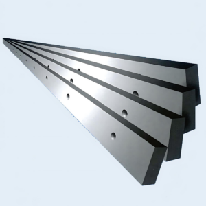
You can grind a razor edge onto a piece of glass. It will glide cleanly through a sheet of paper. But the moment you drive that glass edge into a half-inch plate of hot-rolled steel, it explodes into a thousand costly fragments.
Every day, I see operators pull a damaged blade from a shear, run a thumb across the chipped edge, and conclude that the steel simply went dull. Their first move is to order a harder grade—convinced that more hardness and a keener edge will fix the issue. In reality, they’re treating the symptom while ignoring the root cause.
Think of a heavy-duty truck’s suspension. You wouldn’t install the stiffest quarry-rated springs you can find and expect a smooth ride. Bolt ultra-rigid springs onto a half-ton pickup, hit a pothole with an empty bed, and you’ll rattle the chassis to pieces. The suspension has to be matched precisely to the payload, terrain, and frame.
Shear blades operate on the same principle. If you demand a harder blade without considering what you’re cutting or how the machine delivers force, you’re effectively mounting a glass edge on a guillotine.
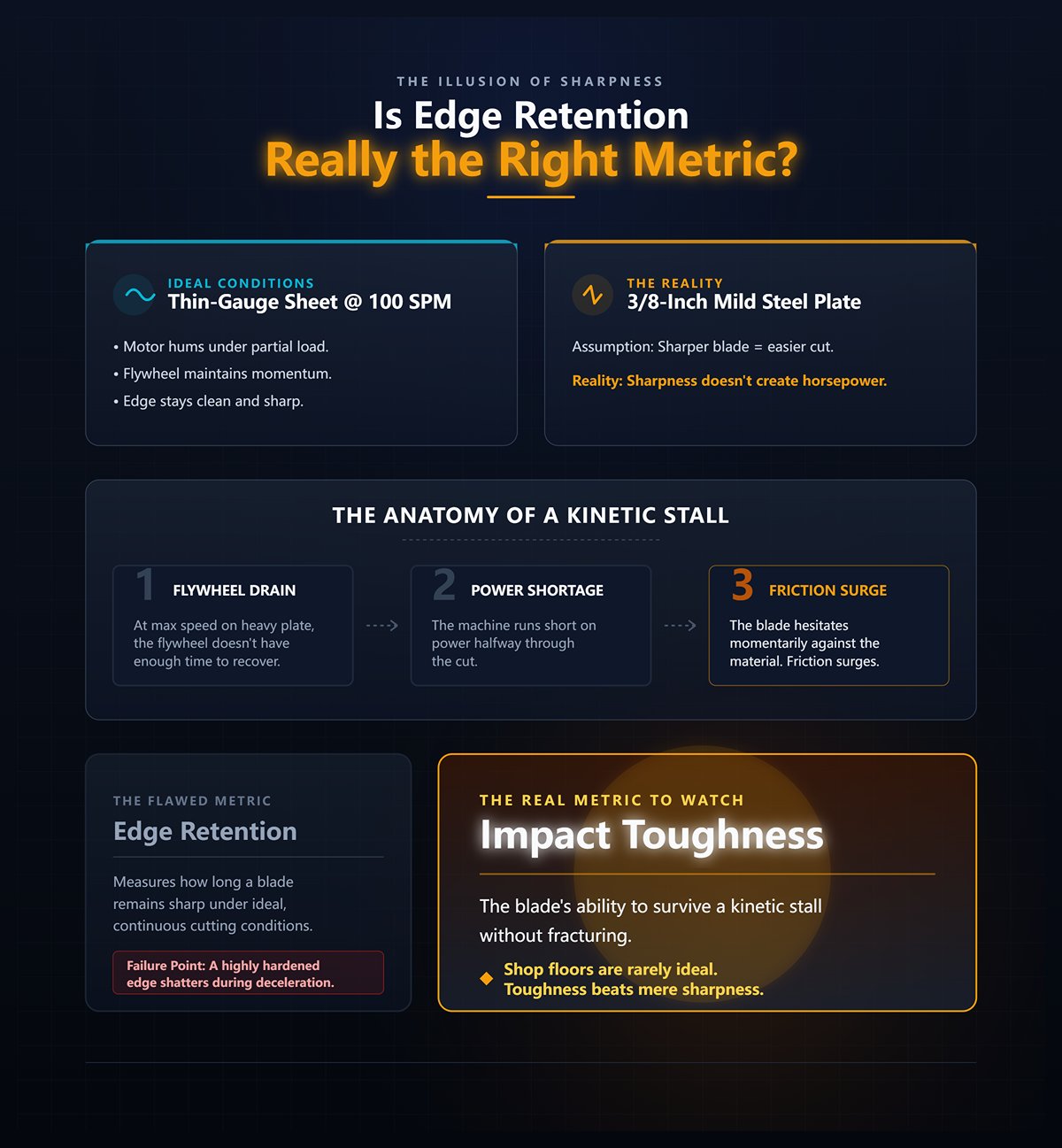
Watch a mechanical shear running at 100 strokes per minute on thin-gauge sheet. The motor hums under partial load, the flywheel maintains momentum, and the edge stays clean and sharp. Now feed that same machine a 3/8-inch mild steel plate. The operator assumes a sharper blade will make the cut easier. But sharpness doesn’t create horsepower.
At maximum speed on heavy plate, the flywheel doesn’t have enough time to recover between strokes. The machine runs short on power halfway through the cut. The blade hesitates momentarily against the material, and friction surges. Edge retention measures how long a blade remains sharp under ideal, continuous cutting conditions. Shop floors are rarely ideal. When a machine bogs down mid-stroke, a highly hardened “razor-sharp” edge can’t absorb that sudden, violent deceleration. The real metric to watch is impact toughness—the blade’s ability to survive a kinetic stall without fracturing.

In 1999, I destroyed a $3,400 set of high-carbon, high-chrome blades on a Cincinnati shear because I thought I knew better than the manufacturer. We were cutting abrasive AR400 plate, and the standard blades were losing their edge too quickly. So I ordered a custom set hardened to a brittle 60 HRC. “Keep them sharp,” I told the apprentice. Two days later, the cut edges on our parts looked like they’d been gnawed by a rat. I pulled the blades, expecting to see dull edges. They weren’t dull at all. Under magnification, the cutting edge had vanished—blown apart into thousands of microscopic fractures.
When you push hardness higher to preserve sharpness, you give up ductility. The blade didn’t gradually wear down; it fractured under preload pressure before the true shearing action even began. Selecting the right metallurgy is crucial; for specialized applications, consider Special Press Brake Tooling which addresses unique material challenges.
Shop-Floor Reality Check: If your sheared edges look rough and torn, but the blade hasn’t been in service long enough to wear out naturally, you’re not dealing with dullness—you’re dealing with brittleness. Stop ordering harder steel.
Take a piece of 1/4″ mild steel. Now pick up a piece that’s 3/8″ thick. You’ve increased the thickness by 50%. Common sense suggests the machine and blade will need to work about 50% harder.
Physics tells a different story. At a fixed rake angle, that 50% increase in thickness can drive the shear load up by as much as 225%.
This is where “close enough” compatibility starts draining profits. An operator sees the machine laboring through thicker plate and decides to increase the rake angle to reduce cutting force and protect the blade’s edge. It works—the blade moves through the material more easily. But higher rake angles introduce significant twist and bow into the cut piece. You may have preserved the edge, but now your fabrication team is spending hours beating the distortion out of parts just to get them flat on the welding table. The blade’s metallurgy, the machine’s geometry, and the material’s demands are locked in a three-way tug-of-war. Change one variable without recalibrating the others, and eventually something gives. So if the steel itself isn’t the real culprit, what actually determines how that blade meets the metal?
I once watched a shop owner spend $4,000 on premium D2 tool steel blades, install them in a hydraulic swing beam shear, and snap the bottom blade in half during the very first shift. He stood there holding the broken pieces, adamant that the steel supplier had shipped him defective material. I examined the machine, then the fractured blade in his hands. What he had purchased was a perfectly square, four-edge blade designed for a straight-drop guillotine shear.
Installing a square-profile blade in a swing beam shear is like bolting heavy-duty one-ton dually truck springs onto a lightweight drag car. You can’t simply choose the stiffest, most robust component on the market and expect optimal performance. When the geometry clashes, the system fights itself—the suspension binds under load, and the chassis ultimately tears apart. A shear blade must be matched precisely to the machine’s stroke mechanics. Otherwise, even the toughest steel available will just fail more quickly. For machines with specific stroke mechanics, such as those from leading brands, ensure compatibility with tooling like Amada Press Brake Tooling or Trumpf Press Brake Tooling.
So why does the machine’s physical motion care so much about the blade’s shape?
In a true guillotine shear, the upper ram travels straight down along vertical gibs. The cutting path is perfectly vertical. When the top blade engages the material, the force vectors move directly upward into the hydraulic cylinders or mechanical linkage. The blade experiences primarily compressive stress—meaning the steel is being squeezed rather than bent.
A swing beam shear operates under an entirely different set of mechanics. The upper ram doesn’t slide down guideways; it pivots on a large hinge pin mounted at the rear of the side frames. As a result, the blade follows a radial arc. During the downward swing, the blade advances slightly forward into the cut, then retracts away from the lower blade as it passes through the shear point.
In 2004, I sheared the brass gibs clean off a mechanical vertical-drop machine because I convinced myself that running thin gauge at 100 strokes per minute would offset a slightly bowed upper blade. I figured the speed would carry the cut through before the bow could cause a bind. Instead, the pure vertical force had nowhere to dissipate laterally. It forced the side frames outward, sidelined us for three weeks, and left us with a staggering repair bill.
Speed can reduce twist in the sheet metal—but it also magnifies deflection within the machine.
If the blade moves in an arc instead of a straight vertical drop, what happens when it collides with the brutal resistance of heavy plate?
| Aspect | Vertical Drop (Guillotine Shear) | Radial Arc (Swing Beam Shear) |
|---|---|---|
| Ram Movement | Travels straight down along vertical gibs | Pivots on a large hinge pin at the rear of the side frames |
| Cutting Path | Perfectly vertical | Follows a radial arc |
| Force Direction | Force vectors move directly upward into hydraulic cylinders or mechanical linkage | Force follows a swinging motion, advancing forward then retracting during the cut |
| Blade Stress Profile | Primarily compressive stress (steel is squeezed rather than bent) | Mixed stresses due to arcing motion and changing blade engagement |
| Blade Engagement | Direct vertical penetration into material | Blade advances slightly forward into the cut, then retracts away from the lower blade |
| Structural Impact Under Load | Pure vertical force has little lateral dissipation; can force side frames outward under extreme stress | Arc motion may distribute forces differently but introduces pivot and hinge stresses |
| High-Speed Operation | Speed can reduce sheet metal twist but magnifies machine deflection | Speed effects depend on pivot dynamics and arc movement |
| Heavy Plate Resistance | Vertical collision concentrates force directly upward through frame and linkage | Arc motion changes how force meets resistance, potentially altering stress distribution |
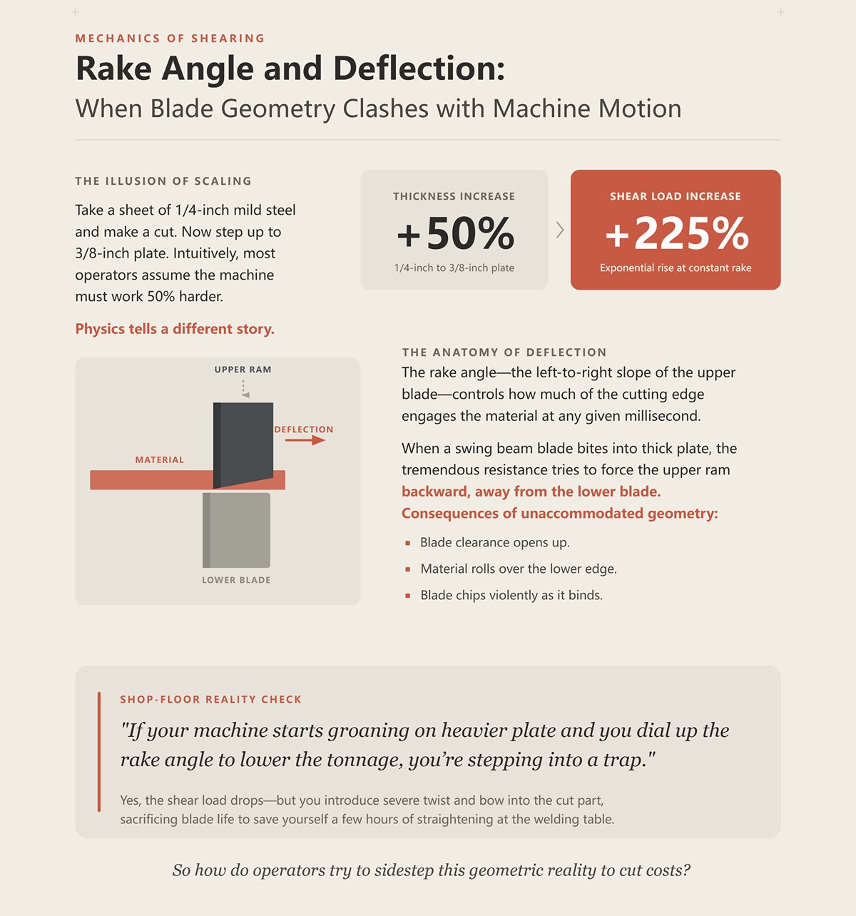
Take a sheet of 1/4-inch mild steel and make a cut. Now step up to 3/8-inch plate. You’ve increased the material thickness by just 50%. Intuitively, most operators assume the machine and blade will need to work about 50% harder to get through it.
Physics tells a different story. With the rake angle held constant, that 50% increase in thickness drives the shear load up by 225%.
The load rises exponentially because the rake angle—the left-to-right slope of the upper blade—controls how much of the cutting edge engages the material at any given millisecond. When a swing beam blade bites into thick plate, the tremendous resistance tries to force the upper ram backward, away from the lower blade. That backward movement is deflection. If the blade geometry isn’t designed to accommodate it, the blade clearance opens up, the material rolls over the lower edge, and the blade chips violently as it binds.
Shop-Floor Reality Check: If your machine starts groaning on heavier plate and you dial up the rake angle to lower the tonnage, you’re stepping into a trap. Yes, the shear load drops—but you introduce severe twist and bow into the cut part, sacrificing blade life to save yourself a few hours of straightening at the welding table.
So how do operators try to sidestep this geometric reality to cut costs?
Everyone wants a four-edge blade. The appeal is obvious: flip it, rotate it, and get four times the cutting life from a single block of tool steel. That approach works perfectly on a guillotine shear, where the blade travels straight down and the back of the blade never contacts the lower die.
But don’t forget the swing beam’s radial arc.
Because the ram pivots on a hinge, the blade sweeps through the cut in an arc. Install a perfectly square, 90-degree block of steel in that arcing ram, and the back heel of the upper blade will drag against the lower blade as it swings past the shear point. To prevent the blades from colliding, swing beam blades require a relief angle—typically a few degrees ground off the back face to clear the lower die.
You simply cannot grind a relief angle on all four sides of a blade.
The geometry simply won’t allow it. The moment you grind a relief on the back to accommodate the arc, you sacrifice the opposing cutting edge. In a swing beam shear, each blade is mechanically limited to two usable edges. When someone tries to cut costs by installing a square, four-edge guillotine blade into a swing beam machine, the result is immediate: on the very first stroke, the back edge slams into the lower blade holder and the tooling is ruined.
The machine’s motion defines the blade’s geometry.
And that geometry determines how the steel must absorb impact. So what happens when the blade’s chemistry isn’t engineered to withstand the physical forces of that specific cut?
Scan the standard tooling charts from any major steel supplier and one hard truth becomes clear: metallurgy is a game of trade-offs. In standardized ratings, a shock-resistant steel like H13 earns a near-perfect 9 out of 9 for impact toughness—but only a 3 out of 9 for wear resistance. Shift to a high-carbon, high-chromium tool steel like D2, and the balance reverses—wear resistance climbs to a 6, while toughness slips to a 5. This inverse relationship is the fundamental rule of shear blade metallurgy. Increase the chromium and carbon to gain hardness and edge retention, and you inevitably increase brittleness as well.
Think of a heavy-duty truck suspension. You wouldn’t bolt on the stiffest one-ton dually springs available and expect a smooth ride from an empty quarter-ton pickup. If the suspension is too rigid for the load, the frame absorbs every punishing shock until it eventually cracks. Shear blades operate on the same principle.
The chemical composition of your tooling has to align precisely with the “payload” of your material thickness and the “terrain” of the machine’s stroke mechanics. If it doesn’t, the entire system will fail under stress. So how do you determine which side of the metallurgical spectrum your shop truly requires? For a wide array of tool steel options tailored to different needs, check out Standard Press Brake Tooling.
In standardized ASTM G65 abrasion tests, D2 tool steel consistently demonstrates far superior wear resistance compared to shock-resistant grades. The reason lies in its chemistry: with up to 1.5% carbon and 12% chromium, D2 forms large volumes of extremely hard chromium carbides within its microstructure. If you’re cutting 20-gauge sheet metal all day, abrasive wear is your primary adversary. As the sheet slides across the blade, it behaves like sandpaper, gradually dulling the edge. In that environment, D2 is in a class of its own. It can maintain a razor-sharp edge for hundreds of thousands of cycles, delivering clean, burr-free cuts over extended production runs.
But sharpness alone doesn’t create horsepower.
The instant you move from thin sheet to heavy plate, the physics of the cut change completely. You’re no longer simply slicing material—you’re exposing the blade to massive, high-energy impacts. The very carbide structures that give D2 its exceptional wear resistance also serve as internal stress concentrators. Under severe shock loading, the steel lacks the ductility required to flex and dissipate the force.
In 1998, I grew tired of constantly rotating blades on a 5/8-inch-capacity mechanical shear that was grinding through hot-rolled mill scale, so I ignored the manufacturer’s specifications and ordered a custom set of D2 blades hardened to 60 HRC. I assumed the added hardness would power straight through the abrasive scale. On the third day of production, an inexperienced operator fed a piece of half-inch A36 plate into the machine with a slight bow along the edge. The ram descended, the blade bound up—and instead of stalling the motor, the upper D2 blade exploded like a fragmentation grenade. A three-pound chunk of tool steel blasted through the safety guard and buried itself in a cinderblock wall twenty feet away. I destroyed a $4,000 set of tooling and nearly killed an apprentice because I valued edge retention over impact resilience.
When the shock load from thick plate exceeds the metallurgical limits of high-carbon steel, catastrophic failure isn’t a remote possibility—it’s inevitable. So if D2 becomes a liability on heavy plate, what actually keeps a blade intact during a violent cut?
To survive heavy shearing, you must let go of the fixation on edge hardness. The metric that truly matters is impact toughness—the blade’s capacity to endure a kinetic stall without fracturing.
This is where S-grade (shock-resistant) steels such as S7—and hot-work steels like H13—come into play. H13 was originally developed to endure the punishing thermal fatigue of aluminum die casting, built to operate at temperatures approaching 700°C and survive rapid water quenching without cracking. In cold metal shearing at room temperature, that heat resistance is largely irrelevant. What matters is that H13 contains roughly 1% vanadium, which significantly enhances crack resistance and structural stability under intense mechanical shock. S7 pushes toughness even further by reducing carbon content to about 0.5%, producing a blade that will dent or roll its edge long before it ever chips or shatters.
When a swing beam shear drives a blade into thick plate, the cut is anything but smooth. For a split second, the blade stalls against the material, hydraulic or mechanical pressure surging until it surpasses the workpiece’s yield strength. That micro-stall sends a shockwave racing back through the blade. Shock-resistant steels are engineered to absorb that impact, offering the ductility required to flex under load without fracturing.
Shop-Floor Reality Check: If you’re using a high-carbon D2 blade to shear half-inch plate simply because it maintains an edge longer on thin material, you’re not cutting metal—you’re assembling a fragmentation device. The moment your machine’s primary task shifts from slicing sheet to fracturing plate, wear resistance must give way to impact toughness. For tooling designed to handle such impacts, explore options like Radius Press Brake Tooling which can distribute stress more effectively.
So is thickness alone enough to justify this metallurgical shift, or does the specific metal being cut fundamentally change the equation?
Many operators assume that because stainless steel feels “harder” to cut than mild steel, it must require a harder blade. That assumption reflects a basic misunderstanding of what’s actually happening along the shear line.
Stainless steel—particularly 300-series grades—contains high levels of nickel, making it extremely gummy and highly susceptible to rapid work-hardening. As the upper blade begins to penetrate, the stainless compresses and hardens directly ahead of the cutting edge. By the time the blade reaches the midpoint of the cut, the material has already changed its mechanical properties, often demanding up to 50% more shear force to fracture than mild steel of the same thickness.
It’s not the workpiece that determines the blade grade—it’s the tonnage required to cut it.
When you shear quarter-inch stainless steel, your machine and tooling absorb a shock load comparable to cutting three-eighths-inch mild steel. Attempting to counter stainless steel’s abrasive, gummy behavior by switching to a harder, more brittle D2 blade is a costly mistake. The dramatically higher tonnage required to fracture work-hardened stainless will simply snap the blade. To withstand the extreme force needed to break the material cleanly, you still need the impact toughness of S7 or H13—even if that means rotating or indexing the cutting edges more frequently as they wear.
You can align your blade’s chemical composition perfectly with the tonnage demands of the material, but metallurgy alone won’t guarantee success. If the physical clearance between the upper and lower blades isn’t precisely calibrated for that specific material and thickness, even the toughest steel available will roll its edge and bring the machine to a halt.
You can invest in the most advanced shock-resistant tool steel on the market, but if your blade clearance is set for 16-gauge and you attempt to shear half-inch plate, you will roll the cutting edge and potentially distort the machine frame. Think of it like a heavy-duty truck suspension. You don’t install the stiffest springs available and expect optimal performance. The payload (material thickness), the terrain (stroke mechanics), and the chassis setup (blade clearance) must be matched precisely. If any one of these three variables is out of sync, the entire system will begin to fail under load. Proper tooling setup is key; for components that aid in alignment, consider Press Brake Die Holder.
When an operator moves from cutting 1/4-inch mild steel to 3/8-inch mild steel, the assumption is often that the machine simply needs to exert slightly more force. After all, the material is only 50% thicker. But the physics at the shear line don’t scale linearly. At the same rake angle, that 50% increase in thickness produces a 225% spike in required shear load.
You’re no longer simply cutting a slightly thicker sheet—you’re confronting an exponential jump in force that can overwhelm conventional blade metallurgy. Shearing thin gauge material is largely an abrasive action. The blade behaves like a pair of scissors, separating the metal cleanly with minimal reactive force. The moment you move into plate steel, however, the physics shift dramatically toward impact and fracture. The upper blade must first penetrate roughly the top third of the plate, generate intense hydrostatic pressure within the steel’s grain structure, and then drive the remaining two-thirds to fracture. That 225% spike in load sends a powerful shockwave straight into the cutting edge.
If the blade is too hard, that nonlinear surge in force will chip or shatter the edge. If it’s tough enough to withstand the impact, it still has to displace a significant volume of steel without seizing. So how does an operator prevent that concentrated burst of energy from destroying the tooling?
The answer is clearance—and it is the most destructive variable an operator directly controls. Setting the blade gap below 7% of the material thickness doesn’t just accelerate wear; it drives a sharp spike in power consumption as the blade attempts to force steel through a space that is simply too narrow.
I learned that lesson the hard way twelve years ago on a hydraulic Cincinnati shear. On a late Friday shift, I let a second-year apprentice set the gap by eye. After running a large batch of 10-gauge sheet, he left the clearance tight and immediately fed a piece of 3/8-inch A36 plate onto the table. The moment he pressed the foot pedal, the S7 shock-resistant blades didn’t just chip. The insufficient clearance caused the plate to bind so aggressively that it friction-welded to the upper blade, stalled the ram, and tore the lower blade seat clean out of the machine bed. That single misadjustment cost me a $6,000 tooling set—and two full weeks of downtime.
Clearance is a non-linear killer of premium steel. When the gap is too wide, the metal doesn’t fracture cleanly—it collapses downward between the blades. That deformed section behaves like a hardened wedge, forcing the upper and lower blades apart laterally. The resulting side load can chip even the toughest H13 edges and leaves behind a rough, heavily burred cut surface. Clearance isn’t static; it must be recalibrated for every change in material thickness. A blade setup that’s “perfect” for one job is only perfect at the exact gap it was designed to run.
Shop-Floor Reality Check: If you’re running multiple plate thicknesses without resetting the blade gap because “it takes too long,” you’re systematically wearing out your tooling. You’re either forcing the machine to crush metal through an artificial choke point or prying it apart over a self-created wedge. To maintain optimal clearance and machine performance, explore accessories like Press Brake Crowning and Press Brake Clamping systems.
So if your material can handle the impact and your clearance is dialed in at a precise 7% of thickness, why do heavy cuts still come off the back of the machine curled like a twisted banana?
Operators often blame dull blades when their drop pieces curl up like potato chips. They pull the tooling, send it out for sharpening, reinstall it—only to get the same warped parts. The mistake isn’t in the edge; it’s in the geometry.
In most cases, the real culprit is rake angle—the slope of the upper blade as it travels across the workpiece. Manufacturers favor steeper rake angles because they reduce the amount of blade in contact with the material at any given moment. That lowers peak shearing force, allowing them to market a smaller, less expensive machine capable of cutting thicker plate. The trade-off? A steep rake behaves like a rolling pin. As it progresses through the cut, it displaces the material unevenly, intensifying twist, bow, and camber in the finished piece. In effect, you’re compromising part quality to reduce required tonnage.
Rake angle isn’t the only mechanical factor that drives distortion. Stroke speed has an enormous impact as well. Mechanical shears, powered by a large rotating flywheel that drives the ram, can reach speeds of up to 100 strokes per minute. That high-velocity impact fractures the metal almost instantly. In contrast, slower hydraulic shears press their way through the cut, giving the steel time to yield, elongate, and twist before finally separating. On identical material, a fast mechanical shear can often eliminate twist and bow that a slower hydraulic machine produces—without changing the blade at all.
If your rake angle is set as flat as the machine allows, your blade gap is precisely dialed in, and your stroke speed is optimized—yet the cut quality is still poor and the blade is chipping—what force is overpowering your entire setup?
You can set a flawless 0.025-inch blade gap with feeler gauges while the machine is powered down. But a shear at rest gives you a false sense of precision.
When the ram descends and that 225% surge in load hits the material, the energy doesn’t flow only into the steel—it transfers into the machine’s frame. On older or undersized shears, the immense tonnage required to fracture thick plate can physically stretch the side frames. The throat of the machine opens. That perfectly measured 0.025-inch static gap instantly expands to a 0.060-inch dynamic gap the moment the blade engages the steel.
The material buckles, the cut edge rolls over, and the operator concludes the blade must have been too soft. In reality, the tooling performed exactly as designed—the machine frame simply deflected away from the cut. You cannot diagnose premature blade failure until you verify that the upper and lower jaws of the machine remain closed under full tonnage.
Imagine building a heavy-duty truck. You wouldn’t just install the stiffest suspension springs available and expect a comfortable ride over a rough logging road. You have to align payload capacity, terrain conditions, and chassis clearance precisely—or the entire vehicle will punish itself under load. [1] Shear blades are no different.
Stop relying on guesswork from a supplier catalog. You can’t fix a mechanical mismatch by simply choosing a harder steel.
Operators love a razor-sharp edge. [2] But sharpness alone doesn’t create horsepower.
Before you even open a tooling catalog, calculate the actual forces at work in the cutting zone. Shear load rises nonlinearly with material thickness. Moving from 1/4-inch to 3/8-inch mild steel may be only a 50 percent increase in thickness, but at the same rake angle it requires a punishing 225 percent increase in shear force.
If your machine doesn’t have the tonnage to handle that surge, the ram stalls, pressure spikes, and the blade absorbs the full kinetic shock. You might try to compensate by reducing the rake angle to flatten the cut, but that increases upper blade engagement and drives the required shear force even higher. At that point, you’re constrained by the physics of the machine frame.
Once you’ve confirmed your available tonnage, align your blade’s steel grade with the material you’re actually cutting. Many operators simply request the hardest blade available, assuming a higher Rockwell rating automatically translates to longer service life.
[3] What truly matters is impact toughness—the blade’s ability to withstand a kinetic stall without fracturing.
I learned this lesson the hard way during a high-volume run of 1/2-inch ductile iron plate. I ordered a custom set of D2 tool steel blades, convinced that their extreme wear resistance would eliminate mid-shift blade changes. What I failed to consider was that highly ductile metals stretch and deform before fracturing, prolonging the preload phase and transmitting sustained shockwaves back into the tooling. On the third day, the lower D2 blade shattered under the repeated impact, sending a fragment through the safety guard and destroying the hydraulic hold-down cylinder. That metallurgical miscalculation cost me a $4,000 blade—and another $2,500 in repairs.
rdness resists wear. Toughness absorbs impact. Choose the property your machine actually requires. For expert guidance on selecting the right tool steel for your application, don’t hesitate to Contact us.
Next, examine the blade’s geometry. Tooling sales reps often promote four-edge reversible blades—four cutting edges sound like double the value of a standard two-edge design.
But that equation only holds in theory. To achieve four functional cutting edges, the blade must be perfectly square. And a square profile, by design, sacrifices the thick, trapezoidal cross-section that gives a two-edge blade its structural strength. If your operation involves high shear forces—such as cutting thick, high-tensile plate on a mechanical shear—that square, four-edge blade will flex and roll under load.
High shear forces accelerate wear no matter how premium the steel grade. In many cases, the true return on investment doesn’t come from adding more cutting edges. It comes from choosing a heavy-duty two-edge blade that resists deflection—and committing to more frequent maintenance to keep it properly honed.
You’ve selected the correct steel. You’ve chosen the proper profile. Now it’s time to mount it and calibrate the machine.
Blade sharpness is just one of six primary variables that determine shear force. The material’s shear strength, cut length, rake angle, stroke speed, and blade clearance are equally critical. As established earlier, blade clearance should be set at roughly 7 percent of the material thickness to achieve optimal cut quality. Stray from that 7 percent, and you’re either crushing the material or forcing the machine apart.
Shop-Floor Reality Check: When an operator says a blade is dull, 90 percent of the time they’re actually dealing with clearance drift. Don’t spend $500 on a regrind until you’ve checked the gap with a feeler gauge and verified it matches the material thickness.
Stop treating consumable tooling as a silver bullet. Start with the machine’s data plate, calculate your true tonnage, match the metallurgy to the impact load, and set the correct clearance. Only then will you stop destroying perfectly good tools.
Throughout this analysis, we’ve dismantled the myth of the “magic” blade. You now understand that tonnage, clearance, and impact toughness determine whether your tooling survives. Yet when cut quality declines, the first instinct on the shop floor is to run a thumb across the blade’s edge, pronounce it dull, and request a sharper replacement. That’s diagnosing a complex mechanical issue with a test meant for pocket knives.
Sharpness is nothing more than the initial edge angle. It tells you nothing about how that steel will behave when 80 tons of hydraulic force drive it through work-hardened stainless plate. If the blade’s backing geometry—the mass and thickness behind that razor edge—doesn’t match your machine’s stroke mechanics, friction alone can double the force required to initiate the cut. You’re not failing because the blade is dull; you’re failing because its cross-section is functioning like a brake pad against the material.
A worn blade deteriorates gradually and predictably over thousands of cycles. A mismatched blade announces the problem on day one. If you’re seeing heavy burrs along the bottom edge of your cut pieces while the blade still feels sharp to the touch, the apex is intact—but the overall tooling geometry is deflecting under load. If the edge begins micro-chipping during the first shift, your alloy’s carbide structure is destabilizing because the steel is too hard for the kinetic shock generated by your specific machine frame.
I once ignored these warning signs on a mechanical shear cutting 1/4-inch AR400 plate. I ordered ultra-hard, mechanically polished martensitic steel blades, expecting them to glide through the abrasive material. Fresh out of the box, they felt slightly rough—which is typical, since mechanical polishing leaves a more aggressive micro-edge on very hard steels—but I assumed they were defective and dull. Instead of trusting the metallurgy, I overcorrected by tightening the blade gap beyond minimum tolerance to force a cleaner shear. On the tenth stroke, the extreme friction behind the edge locked up the cut, shattered the upper blade into three jagged pieces, and tripped the main drive motor’s overload relay. That misunderstanding of edge geometry cost us a $6,000 drive rebuild and two full weeks of downtime.
It’s like installing a high-stall racing transmission in a heavy-duty tow truck. The internal components may be flawless, but the torque curve is completely mismatched to the load—and sooner or later, the housing will crack under the strain.
To break the cycle of buying and breaking, you need to treat replacement tooling as a structural extension of your machine—not a disposable accessory. Run this diagnostic before you place your next order.
First, analyze the geometry behind the cutting edge. Is your machine’s rake angle forcing the thickest section of the blade into the material too early in the stroke? If your required cutting force is climbing, the solution isn’t a sharper tip—it’s a blade with a steeper relief angle to minimize friction and reduce drag.
Second, assess how the alloy’s wear characteristics align with the material you’re cutting. Harder steels can maintain cutting depth two to three times longer under abrasive conditions, but they are more prone to micro-chipping if your machine’s stroke speed introduces excessive kinetic shock. The key is balancing the steel’s carbide structure with the ram’s operating velocity.
Third, recalibrate your expectations about initial bite. A high-hardness blade that’s well matched to your application may actually feel less aggressive out of the box because of the microscopic surface texture left by the grinding process.
Do not allow an operator to reject a new blade based on a simple thumb test.
Shop-Floor Reality Check: If new blades force you to dramatically change your machine’s standard rake angle or clearance settings just to achieve a clean cut in mild steel, remove them immediately. You’re compensating for a tooling mismatch by altering the machine’s mechanical baseline—and sooner or later, the frame will absorb the consequences.
When you contact a tooling supplier, expect them to lead with Rockwell hardness ratings and nominal edge angles. They’ll cite catalog specifications and promise a mirror-polished finish. Cut them off.
Ask this instead: “Can you provide load-tested edge stability data for this specific alloy on a swing-beam shear cutting 3/8-inch stainless steel?”
If they hesitate—or simply repeat the hardness number—end the call. Two blades may measure equally sharp at the apex on a bench test yet behave completely differently under load if their heat treatment responds differently during a kinetic stall. A true tooling expert doesn’t sell sharpness; they sell edge stability under tonnage. They understand precisely how their steel’s microscopic carbide structure behaves when your machine frame flexes, strains, and drives it through thick plate. Buy from the supplier who understands the violence of the cut, and you’ll never have to second-guess a dull edge again.
For a supplier that prioritizes compatibility and performance, explore Jeelix’s comprehensive range of tooling solutions. Download detailed specifications and application guides from our Brochures, and discover specialized products like Euro Press Brake Tooling. Start by browsing our full catalog of Press Brake Toolings to find the perfect match for your machine and material.
 العربية
 বাংলা
বাংলা
 Български
 Čeština
 Dansk
Dansk
 Nederlands
 Suomi
Suomi
 Français
 Deutsch
 Ελληνικά
 עִבְרִית
 हिन्दी
 Magyar
 Bahasa Indonesia
 Italiano
 日本語
日本語
 Қазақ тілі
 한국어
한국어
 Bahasa Melayu
 Norsk bokmål
 فارسی
فارسی
 Polski
 Português
 Română
 Русский
 Српски језик
 Slovenčina
 Español de México
 Español
 Kiswahili
 Svenska
 Tagalog
 தமிழ்
தமிழ்
 ไทย
ไทย
 Türkçe
 Українська
 اردو
اردو
 Tiếng Việt
 简体中文
简体中文
 香港中文
香港中文
 繁體中文
繁體中文