Showing 1–9 of 18 results
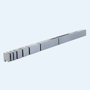
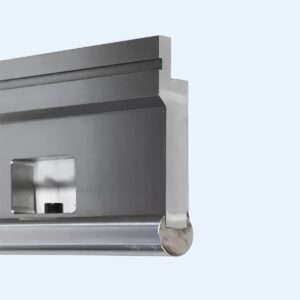
Radius Tool Holder, Radius Press Brake Tooling
Radius Tool Holder, Radius Press Brake Tooling
Radius Tool Holder, Radius Press Brake Tooling
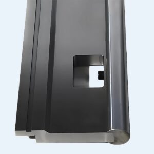
Radius Tools, Radius Press Brake Tooling
Radius Tool Holder, Radius Press Brake Tooling
Radius Tools, Radius Press Brake Tooling
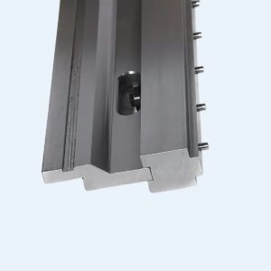
Radius Tools, Radius Press Brake Tooling
Radius Tools, Radius Press Brake Tooling
Radius Tools, Radius Press Brake Tooling
You quoted the job assuming a standard air bend, but the print specifies a large radius. Suddenly, what should have been a quick, 45-second operation turns into a tedious seven-minute process requiring ten individual hits to form a single curve. Many fabricators still consider radius tooling a nice-to-have rather than a must-have, resorting instead to makeshift methods—standard V-dies and step-bending—to fake the desired curve. But this kind of improvisation drives a wedge between the part you promise and the one you deliver, widening a gap filled with hidden labor costs, reduced structural strength, and surface flaws that instantly betray inexperience. For high-performance alternatives, consider upgrading to professional Press Brake Toolings from JEELIX.
The appeal of step-bending—or bump-bending—is easy to see: why invest in specialized radius punches when you can approximate the curve using your existing tools and a series of small incremental hits? Yet the math behind this shortcut exposes a profitability drain that most shops never measure.
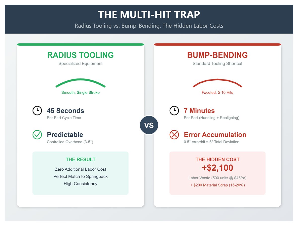
Take, for instance, a batch of 500 units requiring a 10-gauge steel housing with a single R50 bend. With proper radius tooling, each part is completed in one stroke, taking about 45 seconds. Switching to bump-bending means executing multiple hits and repositioning the workpiece repeatedly—typically five to ten times depending on the desired smoothness of the curve.
In real-world production, this multi-hit approach can extend the bending cycle on a one-meter flange to roughly seven minutes per part. The added cost isn’t just in the hits themselves—it’s in the operator’s continuous handling: realigning the sheet, adjusting the back gauge, and visually checking the bend. On a run of 500 pieces, that extra time translates to over $2,100 in additional labor (at $45 per hour).
And that’s only part of the problem. Step-bending introduces error accumulation: even a half-degree deviation per hit adds up, meaning that after ten steps, your final angle can be off by 5 degrees. The result? Higher scrap rates—typically an additional 15–20%—which may add $200 or more in wasted material per batch. Furthermore, crowning compensation often falters on step-bends over two meters, producing fishtailing where the radius tightens or flattens toward the sheet’s ends. By contrast, dedicated radius tooling performs a controlled overbend of 3–5 degrees in a single pass, perfectly matching springback and ensuring predictable results.
When the proper radius punch isn’t available, operators often turn to air bending a sharp punch (R5 or smaller) into a wide V-die (8–12T). Although this setup may reproduce the visual shape of a radius, it significantly undermines the part’s structural integrity.
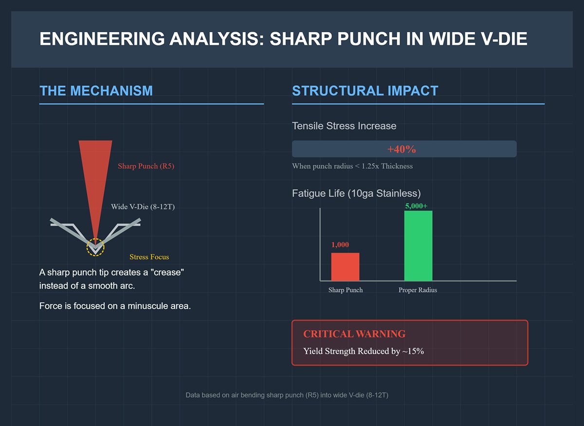
Driving a sharp punch tip into a wide die focuses the entire bending force on a minuscule contact area, creating a crease instead of a smooth arc. Studies show that when the punch radius is less than 1.25 times the material thickness, tensile stress along the outer fiber can increase by 25–40%.
In materials such as 10ga stainless steel, that additional stress exceeds the material’s elongation limit. The failure may not appear immediately, but the structural damage is already there. In fatigue testing, 10ga stainless bent with a sharp punch failed after roughly 1,000 cycles, while the same material formed with a properly matched punch radius (R = V/6 minimum) endured over 5,000 cycles with no micro-cracks. Forcing a sharp tool to perform a radius bend reduces the finished part’s yield strength by about 15%, effectively turning a structural element into a weak point. To avoid this, fabricators can rely on Standard Press Brake Tooling or specialized solutions like Amada Press Brake Tooling.
Every tooling setup leaves its mark on the finished part, and the “orange peel” pattern is a telltale sign of mismatch. It appears as 0.5–1mm wavy ridges or a coarse, alligator-like texture on the convex side of the bend radius.
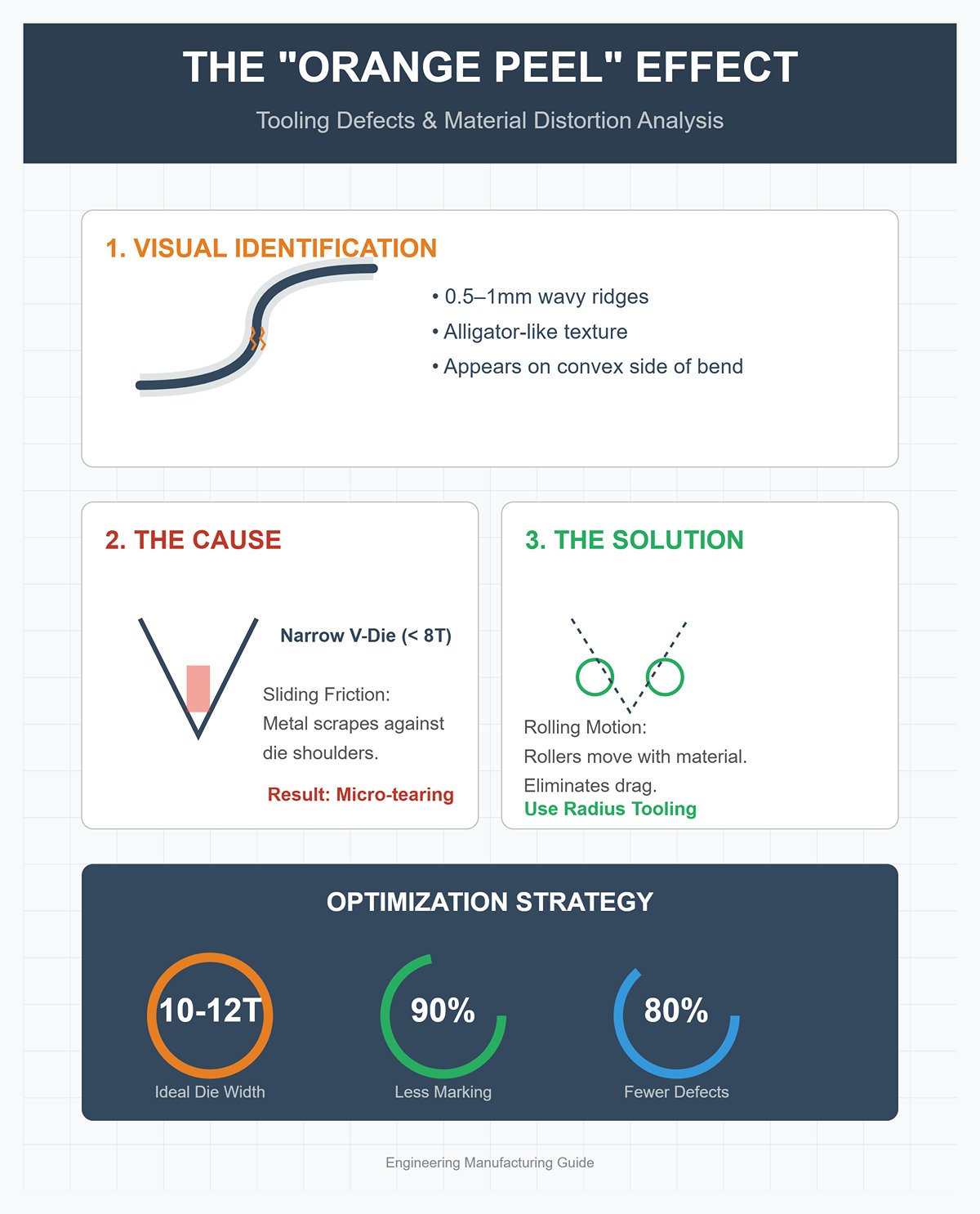
This isn’t a mere aesthetic flaw—it indicates material distortion. Forcing metal into a V-die that’s too narrow (less than 8T of the material thickness) prevents proper material flow. The metal drags along the die shoulders, stretching outer fibers unevenly until they tear at the microscopic level.
Traditional V-dies operate through sliding friction. As the sheet is pressed into the die, its surface scrapes against the die shoulders—an action that can ruin the finish on soft aluminum or polished stainless steel. Radius tooling systems such as the Rolla-V employ precision-ground rollers that move with the material, shifting the contact mechanics from sliding friction to smooth rolling motion.
By evenly distributing force and eliminating surface drag, roller-based tooling reduces part marking by up to 90%. If you observe orange peel on your bends, it likely means the V-die is too narrow or the punch tip is too sharp. Expanding the die width to 10–12T and matching the punch radius can cut the defect rate by roughly 80%, turning what would be rejected parts into visually flawless components. To minimize such issues on large-scale projects, explore advanced Panel Bending Tools.
Many operators approach radius bending as a straightforward geometry exercise—select a punch matching the target radius, bottom the ram, and expect a flawless 90° curve. That’s often the fastest route to scrap. In truth, radius bending is governed by the constant interplay between tensile strength and elastic recovery. Unlike sharp bending, where the punch tip largely defines the inside radius, air bending a wide radius depends primarily on the relationship between the material’s yield strength and the V-die opening. The punch only influences the result—the material’s physics ultimately determine the shape.
To move from trial-and-error to true precision, you must leave behind generic bend deductions and apply the specific mechanical principles governing large-radius deformation.
When forming 10ga (roughly 3 mm) sheet, the “Rule of 8” calls for a 24 mm V-die opening. For mild steel, this is ideal—it produces a natural inside radius around 3.5 mm (just over 1T). But applying the same setup to 10ga 304 stainless steel is a sure path to failure.
Stainless steel has lower ductility and work-hardens far more aggressively than mild steel. While mild steel easily tolerates a tight 1T radius, type 304 stainless typically needs at least 1.5T–2T (about 4.5 mm–6 mm) of inside radius to prevent the outer surface from stretching beyond its limits. Force 10ga stainless into a standard 24 mm V-die, and the outer fibers experience 12–15% tensile strain—enough to produce that telltale “orange peel” finish, an early warning of material fatigue or imminent cracking.
Now compare that to 6061‑T6 aluminum. Although its yield strength (around 250 MPa) rivals mild steel, its plastic deformation behavior allows it to form much tighter bends—down to 1T, and sometimes 0.75T—without suffering the sudden brittleness that plagues stainless.
The Counterintuitive Fix: The key to preventing cracks in 10ga stainless isn’t changing the punch—it’s lowering the strain. Increase your V-die opening to 10T (about 30 mm), which naturally produces an inside radius around 13.5 mm (≈ 4.5T). This adjustment cuts crack risk by roughly 70% while adding only about 15% more tonnage to the forming load.
Radius tooling spreads the bending load across a broader contact area than sharp tooling. While this greatly reduces the risk of cracking, it also intensifies the material’s natural “springback.” Instead of creasing, the metal is curved—meaning much of it remains within the elastic range and instinctively tries to return to a flat state.
The amount of elastic recovery increases with the material’s yield strength. On 10-gauge stainless, a standard 90° air bend often rebounds by 2–3°, leaving a final angle of roughly 87–88°. High-strength steels (comparable to Hardox) can rebound anywhere from 5° to as much as 15°. When you switch to radius tooling, simply programming a 90° bend isn’t enough.
The Overbend Principle: Always program your punch to press slightly deeper than your target angle.
Operators often hit a practical limitation here. If you’re using a large-radius punch—say R50—on 3mm sheet, the formula $V = 2R + 2T$ calls for roughly a 106mm V-die. Using a conventional 88° die may cause the punch to bottom out before achieving enough overbend. A professional workaround is to switch to a 60° or 75° acute V-die for large-radius forming. These provide the clearance needed to push the part past 78°, allowing springback to bring it precisely to 90°.
If you use a conventional K-factor of 0.33 or 0.44 when fabricating a radius bend, your finished dimensions will be off. Those K-values assume that the neutral axis—the layer within the material that experiences neither tension nor compression—sits about 33–44% of the thickness from the inner surface. That model holds for sharp bends where compression at the inner radius is severe.
In contrast, a radius bend produces a gentler curvature. The inner fibers experience less compression, causing the neutral axis to shift outward toward the mid-thickness of the sheet. Once the bend radius equals or exceeds the sheet thickness (R ≥ T), a more accurate K-factor is around 0.5.
The Outcome: If you compute the flat pattern for 10-gauge stainless using K=0.33, you’ll underestimate the required material. The Bend Allowance (BA) is given by:
BA = (2πR / 360) × A × ((K × T / R) + 1)
If you calculate using K=0.33 for a 1.5T bend radius, your bend allowance (BA) might come out to about 3.7 mm. However, using the correct K value of 0.42 or 0.5 raises that to 4.2 mm or more. That seemingly minor 0.5 mm difference per bend quickly adds up. On a U-channel with two bends, the final piece can end up 1 mm short—or the flange lengths can increase—causing gaps and misalignments during welding.
The Shop Fix: Never base your K-factor on the punch tip radius alone. In air bending, the material’s “natural radius” is typically around (V/6). So, if you’re working 3 mm sheet with a 24 mm V-die, the resulting radius will be roughly 4 mm, no matter whether your punch is R3 or R4. Always calculate the K-factor based on that natural radius. For most stainless steel and aluminum applications, start your trial runs at K=0.45—this alone can eliminate about 90% of unnecessary recuts.
A frequent misconception in press brake operations is that radius tooling exists purely for geometric compliance—something you buy only when a drawing specifies a particular inside radius (IR). In truth, radius tooling is a strategic decision that shapes workflow efficiency and profitability. Many operators try to “bump bend” large radii using standard V-dies to avoid investing in dedicated tools—but this shortcut severely cuts into profit on anything beyond initial prototypes. Each bump bend takes multiple hits to approximate a curve that a proper radius tool can produce in one precise stroke.
Choosing the right radius tool goes beyond matching dimensions—it’s about aligning with how the shop runs. Whether your priority is reducing cycle time, juggling a high product mix, or protecting polished surfaces, the tooling must serve your operational goals. Radius tools generally fall into three key categories, each designed to address a specific source of wasted time or cost. You can view detailed specifications in the latest Brochures.
Once a project advances from prototype to production volumes—say, 500 pieces or more—bump bending quickly becomes counterproductive. A solid radius punch and die set is the dedicated solution for high-volume manufacturing, purpose-built to form large radii in a single, clean hit. Discover more professional-grade options such as Wila Press Brake Tooling and Trumpf Press Brake Tooling.
The case for using solid sets is grounded in time efficiency. Converting a multi-step bump bend into one smooth stroke typically cuts cycle time by about 40% on 6–12 mm low-carbon steel. These tools are precisely engineered for controlled bottoming or air bending, enabling operators to produce consistent 90° bends without the trial-and-error typical of step bending.
Solid radius punch and die sets excel in producing consistent results for structural components such as trailer flanges or heavy ductwork, where uniformity takes precedence over flexibility. When properly paired, these tools enable controlled overbending—typically forming to about 78° to offset springback and finish precisely at 90°. This level of predictability is vital when operating near 80% of the press brake’s rated tonnage. By matching the punch nose radius to the material thickness (targeting an inside radius approximately 1.25 times the thickness for 10-gauge steel), solid tooling brings stability to the process, converting what could be a complex forming task into a repeatable, standardized operation.
For job shops that handle a high mix of low-volume orders, buying a dedicated solid steel tool for every unique radius quickly becomes cost-prohibitive. One day, a shop might need a 1-inch radius for an aluminum prototype; two days later, a 2-inch radius for a heavy steel bracket. Investing $5,000 per piece for seldom-used tools locks up capital and floor space that could be better spent elsewhere.
Modular insert holders address this challenge by decoupling the wear surface from the tool body. These systems use a standardized holder fitted with interchangeable hardened inserts—typically covering radii from 1/2 inch to 4 inches. This configuration generally costs 30–50% less than purchasing comparable solid tools and drastically shortens lead times, with inserts often delivered in two weeks instead of the six to eight weeks required for custom solid tooling.
The benefits extend beyond initial cost savings. In any high-impact forming process, tool wear is inevitable. With solid tooling, a worn radius usually demands complete remachining or scrapping the entire tool. Modular systems isolate wear to the replaceable insert; after about 1,000 hits or noticeable abrasion, the operator simply swaps out the contact surface while retaining the main holder. This makes modular tooling an ideal solution for shops that need to accommodate diverse customer specifications while maintaining a lean, economical tooling inventory.
When the design calls for flawless surface quality—think polished aluminum housings, pre-painted stainless HVAC flanges, or high-end architectural panels—standard steel tooling adds a hidden expense: post-process finishing. Conventional steel V-dies often leave behind telltale impressions, light galling, or subtle texture distortions along the radius. Correcting these imperfections typically demands manual buffing or re-finishing, tasks that can consume 20–30% of total production time.
Urethane dies (like Acrotech’s K•Prene®) solve this issue by replacing the rigid steel contact surface with a high-strength polyurethane pad. Instead of forcing the metal to flow through friction and pressure points, the urethane flexes around the material, evenly distributing the forming load. This prevents the imprint lines or shoulder pressure marks common with steel dies. Despite their elastic nature, urethane dies are impressively tough—they can form 10- to 14-gauge steel or aluminum under standard air-bend forces. Many shops even report up to five times the service life on abrasive materials, such as prefinished galvalume, compared to steel tooling. See additional finishing options in Shear Blades and Laser Accessories.
For applications demanding absolutely no surface blemishes, seasoned fabricators often pair urethane dies with a 0.015″–0.030″ MarFree urethane protection film. This thin overlay acts as a barrier between the sheet and the die, stopping even microscopic scuffs on mirror-finish stainless or pre-painted metals. While the urethane die itself eliminates physical indentation, the added film protects both the workpiece and the die from edge cuts, extending tool life under heavy or sharp-edge service. If a shop finds itself scrapping more than 5% of parts due to cosmetic flaws—or if post-bend polishing slows the entire line—switching to urethane tooling is the clear solution.
| Tool Type | Description | Ideal Applications | Key Benefits |
|---|---|---|---|
| Solid Radius Punch and Die Sets | Dedicated tooling designed for forming large radii in a single operation, optimized for high-volume production. | Structural and heavy components such as trailer flanges, heavy ductwork, and parts requiring consistent 90° bends. | – Up to 40% cycle-time reduction compared to bump bending on 6–12 mm low-carbon steel. – Consistent, repeatable bends through controlled bottoming or air bending. – Enables controlled overbending (≈78° to compensate springback). – Matches punch nose radius to material thickness (≈1.25× thickness for 10-gauge steel). |
| Modular Insert Holders | Standardized holders with interchangeable hardened inserts for varying radii (typically from ½” to 4″). | Job shops or manufacturers handling a wide variety of short-run parts requiring custom radii. | – 30–50% lower cost than solid tools. – Shorter lead times (≈2 weeks vs. 6–8 weeks for custom tools). – Replaceable inserts isolate wear, extending tool life. – Reduces capital investment and storage requirements. |
| Urethane Dies | High-strength polyurethane dies that flex around the material, preventing surface marks and pressure lines. | Cosmetic or appearance-critical parts like polished aluminum, pre-painted stainless, or architectural panels. | – Eliminates die marks and surface defects. – Can form 10- to 14-gauge steel or aluminum. – Up to 5× service life on abrasive materials. – Compatible with MarFree film for zero blemishes and extended die protection. |
Many operators mistakenly believe that producing a consistent, high-quality radius means forcing the material completely into the die to “lock in” the curve. That approach might work for light-gauge sheet, but applying it to 0.25-inch (6 mm) or thicker plate is a recipe for disaster. Bottoming heavy material transfers massive stress to the press—often enough to distort or crack the frame itself.
True accuracy in thick-radius bending comes down to geometry, not sheer power. By using air bending rather than coining, you can cut the required tonnage by as much as 90% while still holding tolerance. Mastering the interplay of die ratios and force multiplication is the only way to avoid the so‑called “tonnage trap” — the fine line between a smooth, repeatable setup and a catastrophic press failure.
Standard press brake tonnage charts can be misleading because they nearly always show the force needed for air bending mild steel (usually rated at 60,000 PSI tensile strength). Operators see a seemingly easy figure, assume it’s safe, and then bottom the punch to form the radius more cleanly. What they overlook is the exponential jump in required force once the material begins compressing between the punch and die.
As a baseline, air bending uses a factor of 1x. Bottom bending demands roughly four times that force, and coining can require up to ten times more.
Take a practical example: bending an 8‑foot sheet of 0.25‑inch mild steel using a standard 2‑inch V‑die.
Trying to coin that radius on a 250‑ton press brake means the machine will either stall or sustain major structural damage long before the bend completes.
Material variability compounds the challenge. Stainless steel needs roughly 160% of the tonnage required for mild steel, while soft aluminum requires only about 50%. And since steel mills certify material by minimum yield strength, a batch labeled as A36 could easily have a tensile range of 65–72 ksi instead of the rated 58 ksi.
Shop Tip: Calculate your tonnage from the chart’s air‑bend value, then add a 20% safety margin. This compensates for friction from the large contact area of radius tooling and inevitable variations in plate strength. So, if the chart shows 100 tons, plan for 120. And if your press is rated at 120 tons, you’re already approaching danger territory.
Choosing the right V-die opening is less about brute force and more about geometry. In radius bending, the part’s internal radius (Ir) during air bending is mainly determined by the die width. Generally, it correlates to a percentage of the die opening—about 16–20% for standard V-dies—though radius-specific dies behave somewhat differently.
For materials thinner than 0.25 inches, the standard 8T rule (die width = 8 × material thickness) generally works well. But once you move into plate stock (0.25 inch / 6 mm or thicker) or higher-strength materials like Weldex, sticking rigidly to the 8T ratio dramatically increases required tonnage and the risk of tooling collisions.
If the die opening is too narrow, a large-radius punch won’t be able to descend far enough to achieve the target bend angle without pressing the material into the die shoulders. At that point, the process shifts from bending to forming or stamping—instantly tripling the tonnage demand.
The Counterintuitive Advantage: Expanding your die opening from 8T to 10T or 12T is often the most effective way to cut down on tonnage, even more so than upgrading to costly tooling.
Follow this sizing guide to prevent tool collisions and overloading:
Formula Note: The approximate inside radius from an air bend is calculated as Ir = (V – MT) / 2. If you need a tighter radius than the die naturally produces, adjust the die width—don’t compensate by forcing the punch deeper.
Tonnage increases proportionally with bend length. A setup that works perfectly on a 2-foot test piece can permanently distort the ram when scaled up to a 10-foot production run. Long-radius bends are particularly vulnerable to “canoeing,” where the press beam bows in the middle under load, producing a bend that’s too tight at the ends and too open at the center.
Radius tooling distributes force over a wider area than standard acute punches, which can create uneven loading across the beam. If you overlook crowning on a 10‑gauge stainless steel part with a 2‑inch radius, the beam can twist between 2 and 5 degrees. This distortion compels the operator to shim the die or over‑bend the center, leading to inconsistent results and potentially scrapping around 20% of the batch.
Before performing a long‑radius bend (over 8 feet), run through the following protection checklist:
1. Verify Die Ratio: Make sure you’re using a 10T setup for material 0.25 inches thick or more. If you’re at 8T, stop. The extra friction across 8 feet or longer will likely exceed the machine’s rated load capacity.
2. Check Punch Radius vs. Inside Radius (Ir): The punch radius should be slightly smaller than the natural air‑bent radius produced by the V‑die. If the punch is larger than that natural radius, it will contact the sides of the material before achieving the desired bend angle, forcing the machine to coin rather than air‑bend.
3. Calculate Total Tonnage with Margin: Determine the tonnage per foot for an air bend, multiply by the overall bend length, then add a 20% buffer for friction and material variation. If the total exceeds 70% of your press’s rated capacity, you’re in deflection territory.
4. Set Crowning Before Bending: For radii larger than one inch, plan for about 3° of springback. Don’t wait for the first bad part to appear. With CNC crowning, base your compensation on the actual tonnage calculation, not just material thickness.
5. Confirm Flange Length: Verify that your flange meets the minimum dimension formula (V / 2) + Stroke Allowance. A flange that’s too short can slip into the die during the extended rotation of a radius bend, damaging tooling and possibly ejecting the workpiece.
The priciest tool in the shop isn’t always the one you purchase—it’s the one you try to replicate by taking twenty hits with a standard V‑die. Bump bending (also called step bending) might seem cost‑free because it uses existing tooling, but it imposes a hidden cost known as the Bump Penalty.
For thicker materials, that penalty can triple your labor time. A cylinder or wide‑radius flange that takes three to five strikes to rough out a curve consumes roughly 300% more operator hours than a dedicated radius tool. Each extra hit also adds variability—more chances for angular drift and extra springback adjustments that slow down your workflow.
The 50‑Part Rule
You can determine your plan of action before even quoting the job. Use this production volume threshold as your go/no‑go trigger:
Many fabricators greatly overestimate the breakeven point for custom tooling, assuming it takes tens of thousands of parts. In reality, one substantial production run can often cover the investment.
To find out whether you should issue a purchase order today, grab a recent work order and run this quick “napkin ROI” calculation:
The Result: You need only about 1,800 parts to recover the full tool cost.
If you have a repeat job of 150 parts per month, the tool pays for itself within a year. From year two onward, that saved $2.50 per part shifts straight from “labor expense” to “net profit.”
Take the example of a Midwest structural fabricator who stopped outsourcing their heavy radiused plate work. By investing in a dedicated setup for their 1,200‑ton press brake, they not only recovered tooling costs but also eliminated vendor markups and shipping delays. That move unlocked higher‑margin structural beam projects and boosted their profitability by 30%.
If you’re paying more than $5.00 per part for outsourced radiused pieces, bringing the work in-house delivers an instant return on investment. In fact, the numbers make it clear: purchasing the right tooling doesn’t cost you money—keeping up with bump bending is what’s truly eating into your profits. For expert consultation or a custom tooling quote, Contact us today to discover the best-fitting solution for your press brake.
 العربية
 বাংলা
বাংলা
 Български
 Čeština
 Dansk
Dansk
 Nederlands
 Suomi
Suomi
 Français
 Deutsch
 Ελληνικά
 עִבְרִית
 हिन्दी
 Magyar
 Bahasa Indonesia
 Italiano
 日本語
日本語
 Қазақ тілі
 한국어
한국어
 Bahasa Melayu
 Norsk bokmål
 فارسی
فارسی
 Polski
 Português
 Română
 Русский
 Српски језик
 Slovenčina
 Español de México
 Español
 Kiswahili
 Svenska
 Tagalog
 தமிழ்
தமிழ்
 ไทย
ไทย
 Türkçe
 Українська
 اردو
اردو
 Tiếng Việt
 简体中文
简体中文
 香港中文
香港中文
 繁體中文
繁體中文
