Showing 1–9 of 12 results
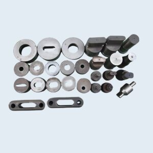
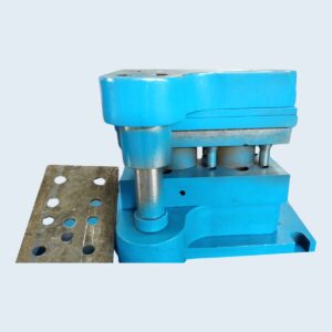
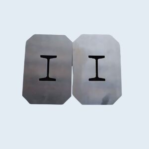
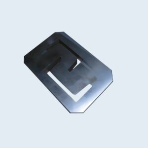
Punching & Ironworker Tools
Punching & Ironworker Tools
Punching & Ironworker Tools
Punching & Ironworker Tools
Punching & Ironworker Tools
Punching & Ironworker Tools
Punching & Ironworker Tools
Punching & Ironworker Tools
Punching & Ironworker Tools
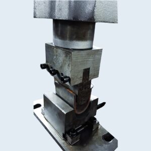
You slide a 1-1/16″ punch into the holder. It fits—flush, snug, seemingly perfect. You tap the foot pedal, expecting a clean slug to fall free. Instead, there’s a sharp, gunshot crack, a seized ram, and shards of hardened tool steel skittering across the shop floor.
You assumed that if a punch fits the holder, it fits the machine. In a fabrication shop, that assumption can be the most expensive one you make. Drill presses and impact drivers condition us to expect universal shanks and interchangeable tooling. But an ironworker isn’t a drill press. When you treat 50 tons of hydraulic shearing force like a cordless driver, you don’t just botch the cut—you misunderstand how the machine actually transmits power. For a comprehensive understanding of precision tooling systems, exploring resources from a specialist like Jeelix can provide valuable insights into proper tool selection and compatibility.
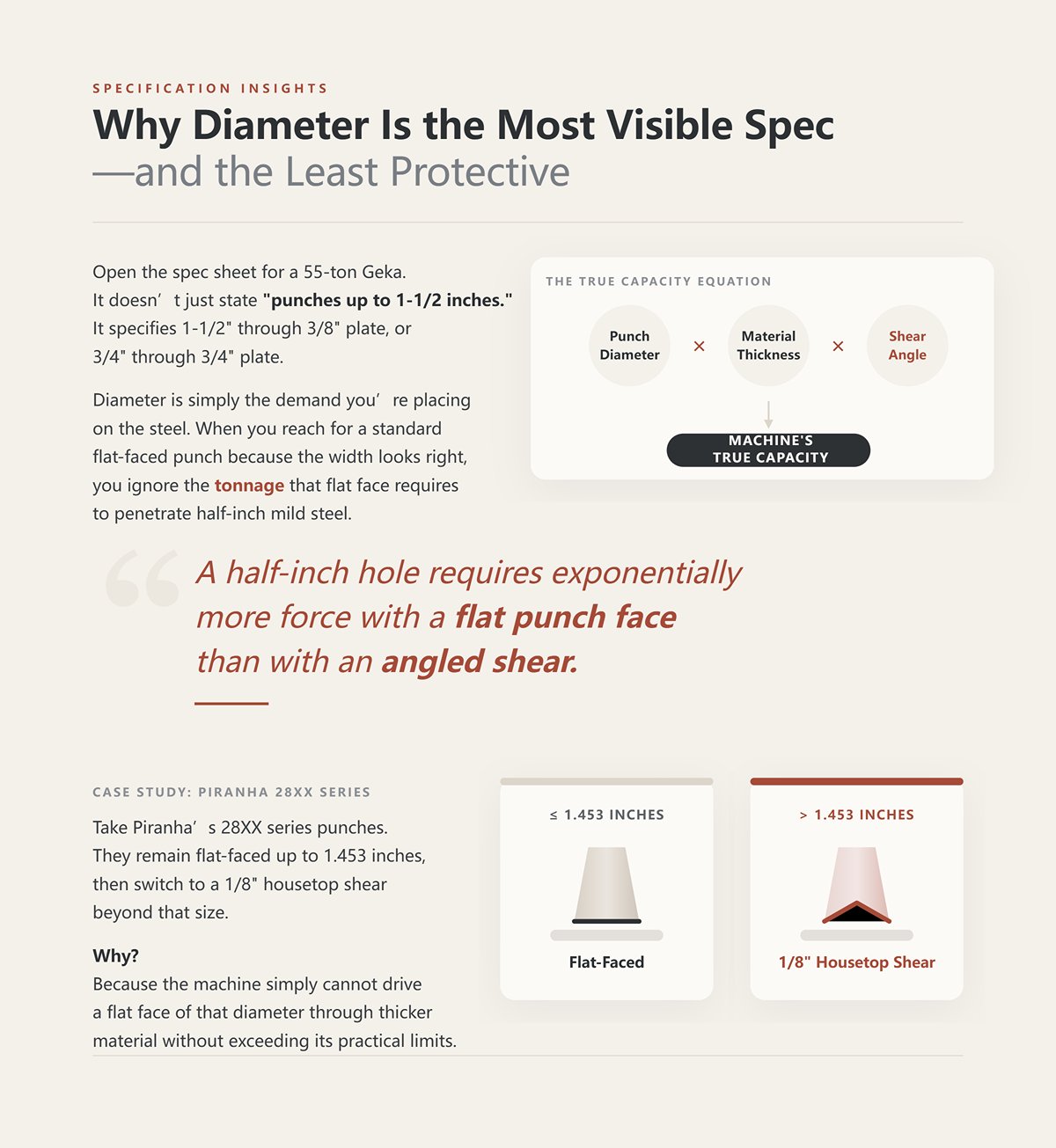
Open the spec sheet for a 55-ton Geka. It doesn’t just state “punches up to 1-1/2 inches.” It specifies 1-1/2″ through 3/8″ plate, or 3/4″ through 3/4″ plate. Diameter is simply the demand you’re placing on the steel. The machine’s true capacity is defined by the interaction between punch diameter, material thickness, and the shear angle ground into the punch face. When you reach for a standard flat-faced punch because the width looks right, you ignore the tonnage that flat face requires to penetrate half-inch mild steel. This principle applies broadly, whether you’re working with ironworker punches or Standard Press Brake Tooling—understanding geometry is key.
A half-inch hole requires exponentially more force with a flat punch face than with an angled shear.
Take Piranha’s 28XX series punches. They remain flat-faced up to 1.453 inches, then switch to a 1/8″ housetop shear beyond that size. Why? Because the machine simply cannot drive a flat face of that diameter through thicker material without exceeding its practical limits.
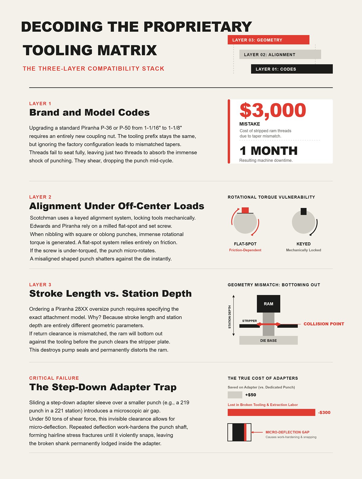
Pull the manual for a standard Piranha P-36 or P-50. You’ll find a subtle but critical note: upgrading from a 1-1/16″ to a 1-1/8″ heavy-duty punch requires an entirely new coupling nut. The tooling prefix stays the same. The catalog lists both punches within the same family. But if you ignore your machine’s factory configuration and force the larger punch into the original nut, you’re setting yourself up for failure. This highlights the importance of brand-specific compatibility, a principle that extends to other major brands like Amada Press Brake Tooling, Wila Press Brake Tooling, and Trumpf Press Brake Tooling.
Machinists scan a DH/JC tooling chart, measure a shank with calipers, and assume that matching diameters mean matching tools. What they overlook is the taper. Force a slightly mismatched prefix into a holder and the threads may grab—but they won’t fully seat. That leaves two threads trying to absorb the shock of punching through half-inch plate. They shear. The punch drops out of the ram mid-cycle. The hydraulic cylinder then crashes down onto a loose block of hardened steel. Stripping the ram threads because you trusted a catalog prefix instead of verifying your machine’s actual configuration is a $3,000 mistake—and a month of downtime. If you’re ever unsure about compatibility, it’s always best to Contact us for expert guidance rather than risk your machine.
Scotchman ironworkers use a keyed alignment system across all shaped punches, locking each tool into the ram with a dedicated keyway. Other brands—such as Edwards and Piranha—typically rely on a milled flat on the punch shank secured by a heavy set screw to prevent rotation. If you’re punching round holes dead center in a baseplate, the distinction is largely irrelevant. Round holes are indifferent to rotational alignment.
The moment you switch to an oblong or square punch to nibble along the edge of a gusset, the physics change. Nibbling concentrates the entire shear load on one side of the punch face, generating significant rotational torque. A flat-spot system depends entirely on the friction of that single set screw to resist the twist. If the operator under-torqued the screw—or if years of use have worn the flat—the punch can rotate a fraction of a degree just before contacting the material. The square punch descends slightly out of square with the square die. Driving a shaped punch into a misaligned die sends fragments of tool steel flying at chest height and destroys both punch and die in an instant.
Order a 28XX series oversize punch from Piranha—anything up to 5 inches in diameter—and the factory requires you to specify the exact oversize attachment model installed on your machine. They’re not just asking for tonnage. They need the attachment model because stroke length and station depth are two entirely different parameters.
You can mount a 4-inch punch on a machine with a 2-inch stroke and it will still pass through the plate. But if the station depth on that specific attachment doesn’t align with the punch’s required return clearance, the ram will reach the end of its travel before the punch clears the stripper plate. I once tore down a jammed ram where the punch head resembled a crushed soda can—the flanges had sheared off cleanly, and the core had collapsed into a fractured, useless mass of D2 steel. The operator had assumed that matching diameters meant compatible stroke geometry. They don’t. Bottoming out a hydraulic cylinder against mismatched tooling can destroy pump seals and permanently distort the ram.
Slide a DH/JC step-down adapter sleeve over a smaller punch to run it in a larger station, and it can feel like you’ve outsmarted the system. Take a 219 punch, slip on the sleeve, and operate it in a 221 station. The fit feels tight. The set screw is secure.
But an adapter inevitably introduces a microscopic air gap and tolerance stacking between the ram and the tool. Under 50 tons of shear force, metal shifts and deforms. That nearly invisible clearance allows the punch to deflect slightly under load. It may survive the first heavy plate. Over dozens of cycles, however, that repeated micro-deflection work-hardens the punch shaft, forming hairline stress fractures at the collar. Then it snaps—often while punching something as light as 1/8″ sheet—leaving the shank lodged inside the adapter. Saving fifty dollars by using a step-down adapter instead of a dedicated punch often turns into three hundred dollars in broken tooling and extraction labor.
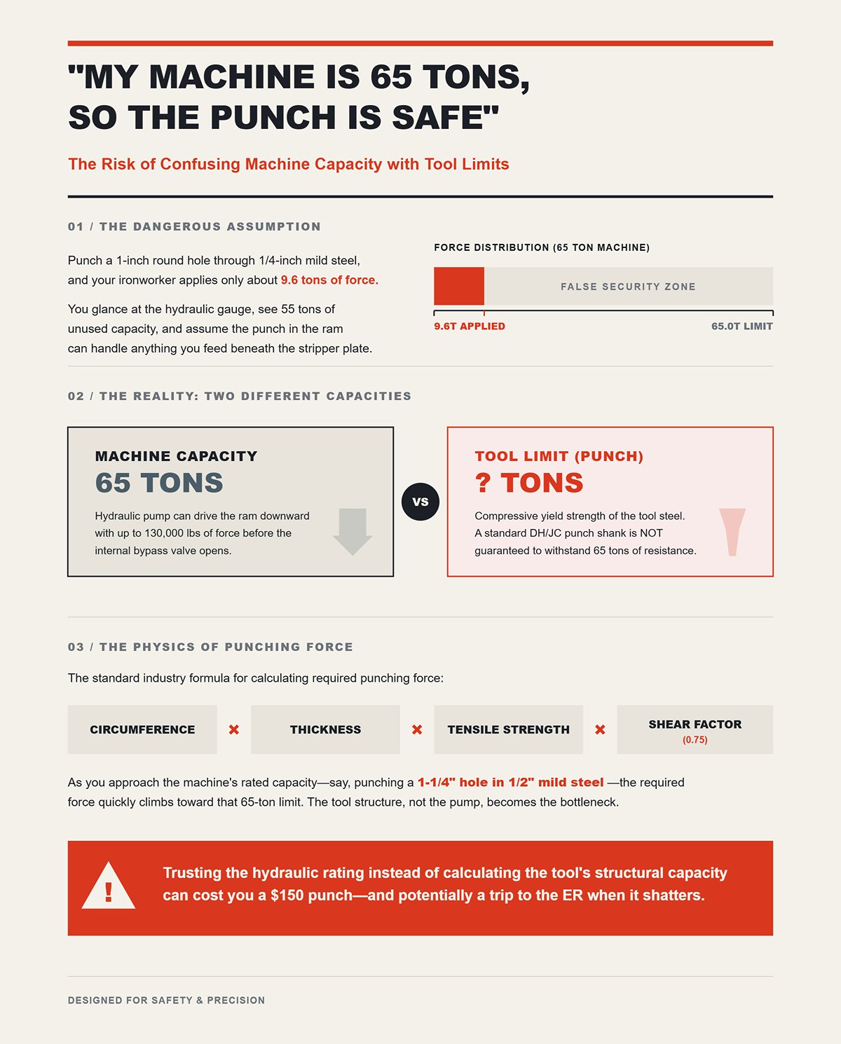
Punch a 1-inch round hole through 1/4-inch mild steel, and your ironworker applies only about 9.6 tons of force. If you’re operating a 65-ton machine, that calculation can make you feel untouchable. You glance at the hydraulic gauge, see 55 tons of unused capacity, and assume the punch in the ram can handle anything you feed beneath the stripper plate.
That assumption is exactly where the trouble begins.
A 65-ton rating means only one thing: the hydraulic pump can drive the ram downward with up to 130,000 pounds of force before the internal bypass valve opens. It says nothing about the compressive yield strength of the tool steel mounted to that ram. The standard industry formula for punching force multiplies the punch circumference by the material thickness, the plate’s tensile strength, and a 0.75 shear factor. As you approach the machine’s rated capacity—say, punching a 1-1/4″ hole in 1/2″ mild steel—the required force quickly climbs toward that 65-ton limit. But just because the machine can generate 65 tons doesn’t mean a standard DH/JC punch shank can withstand 65 tons of resistance. Trusting the hydraulic rating instead of calculating the tool’s structural capacity can cost you a $150 punch—and potentially a trip to the emergency room when it shatters.
Check the tonnage chart riveted to the side of your machine and you’ll see figures based on standard 65 ksi mild steel. Yet when a machinist slides a piece of 1/4-inch 304 stainless under the ram, they often glance at the thickness on the mild steel chart and step on the foot pedal without a second thought.
What they overlook is that stainless steel pushes back.
Stainless steel doesn’t passively shear—it work-hardens the instant the punch makes contact. The material compressing ahead of the punch tip rapidly becomes harder than the surrounding plate. To break through that localized hardened zone, you need to apply a 1.50× force multiplier to your baseline mild steel calculation, plus a 1.30 safety factor to account for alloy variability and tool wear. A hole that required 20 tons in mild steel can suddenly demand more than 39 tons in stainless. If you’re running a standard 219 series punch without accounting for that dynamic hardness spike, the hydraulic ram will continue to apply force until the tool steel fails. Ignore the math on work-hardening alloys, and you may spend the afternoon extracting a seized punch from a distorted stripper plate—while the shop owner fumes over the replacement cost.
A round punch distributes compressive stress evenly around its entire circumference. The instant you switch to an oblong or figure-8 punch to cut a keyhole, that ideal symmetry disappears.
To offset the longer perimeter of an oblong profile, tooling manufacturers grind a rooftop shear angle into the punch face. This geometry allows the punch to enter the material progressively, reducing the effective thickness being sheared at any given moment and cutting required tonnage by as much as 50% in thin stock. But drive that same angled punch into half-inch plate, and the physics turn unforgiving. The high points of the shear angle engage first, generating substantial lateral deflection forces that try to bend the punch shaft sideways before the rest of the face even makes contact. For specialized forming tasks that require precise radii or unique profiles, dedicated tooling like Radius Press Brake Tooling or Special Press Brake Tooling is engineered to manage these complex forces.
I once conducted a post-mortem on a shattered 28XX figure-8 punch that someone tried to force through half-inch A36 plate. The tool didn’t fail at the cutting edge. Instead, lateral stress from the shear angle concentrated at the narrowest section of the figure-8 web, snapping the punch cleanly in half horizontally while the upper portion remained bolted to the ram. Ignore the lateral deflection caused by shear angles on non-round tooling, and you’re setting yourself up for a fractured ram—and a face full of hardened shrapnel.
You can calculate tonnage with precision and seat a DH/JC punch so tightly it feels fused to the ram, but if the opening in your bottom die is mis-sized, the workpiece will still suffer.
Take a look at the slugs in your scrap bin after punching 1/4-inch mild steel. If you notice a wide, polished burnish zone, sharply angled fracture lines, and minimal rollover along the top edge, your die clearance is too tight. When the punch strikes the plate, it doesn’t simply slice through—it drives the material downward until the steel’s tensile strength is exceeded and it fractures. That break creates a crack that propagates downward from the punch tip, while a second fracture line rises from the edge of the bottom die. When clearance is properly set—typically around 1/16 inch for this thickness—those two microscopic fracture lines intersect precisely at mid-thickness. The slug releases cleanly, and the resulting hole wall is smooth.
But when you tighten that clearance down to 1/32 inch on a 13/16-inch punch, those fracture lines never intersect.
The metal is forced to shear twice. That double shear produces a rough, torn edge inside the hole and drives excess material outward, leaving an ugly rolled burr on the surface of your otherwise flat 1/4-inch plate. At that point, you’re no longer cutting steel—you’re crushing it into submission. Forcing a punch through an overly tight die gap will leave you with a warped stripper plate and a scrap part before the shift is half over.
Old-school shop manuals insist on a strict 10% total clearance rule for mild steel. On 1/4-inch plate, that translates to a 0.025-inch gap between the punch and die. Run that tight 10% clearance and you’ll get a clean, sharp hole with minimal edge rollover. But hole quality is only half the equation—because what goes down has to come back up. With a 10% clearance, the hole contracts microscopically around the punch the instant the slug breaks free, turning the return stroke into a high-friction tug-of-war.
Stripping force is the silent killer of punch tooling.
Open that die clearance to 15% or even 20%, and hole quality will decline slightly—you’ll see a bit more rollover and a rougher fracture zone. But the punch can finally breathe. Stripping loads on the tool steel drop dramatically because the wider die gap allows the material to fracture earlier in the stroke, reducing the elastic springback that clamps onto the punch shank. Just last month, I examined a shattered 219 series punch where the operator had run a 5% clearance on half-inch plate. The tool didn’t fail on the downstroke—it friction-welded itself on the return, and the stripper plate tore the punch head clean off the shank. Chasing a mirror-finish hole with razor-thin clearances on concealed structural baseplates can easily cost you hundreds of dollars a week in broken tooling.
Now slide a sheet of AR400 wear plate or 60,000 psi high-tensile steel into that same setup, and the rules that worked for mild steel become a liability. High-tensile alloys don’t flow—they resist the shearing force, building extreme heat and pressure at the cutting edge before finally fracturing with a snap. If you stick with your standard 10% to 15% die clearance on AR plate, that concentrated pressure can cause the material to cold-weld to the punch walls—a phenomenon known as galling.
In effect, the clearance closes up on you.
Once galling begins, the punch grows microscopically thicker with every stroke, increasing drag against the die until frictional heat destroys the tool’s temper. With high-tensile alloys, you need to increase die clearance to 20% per side—or more—so the metal can fracture cleanly without welding itself to your tooling. And if your intended hole diameter is smaller than the material thickness in 60,000 psi steel, don’t punch it at all. The compressive force required to initiate the shear will exceed the yield strength of the tool steel long before the plate gives way. Trying to punch a hole smaller than the material thickness in high-tensile steel is a guaranteed recipe for catastrophic tool failure—and a potential trip to the emergency room.
Have you ever looked down at a dustpan full of shattered tool steel and wondered what it was trying to tell you? A broken punch isn’t random bad luck—it’s an itemized invoice. Every jagged fracture, every sheared collar, every crushed tip documents exactly which part of the three-layer compatibility rule you ignored. When a tool tears itself apart, it leaves behind a physical record of the forces that destroyed it. The key is learning how to read the evidence.
Start at the working end. If you remove the tool and find the cutting tip obliterated—flattened, mushroomed, or snapped off at a sharp angle—you demanded something from the steel that physics wouldn’t permit. That’s an overload failure. Either you attempted to punch high-tensile plate with a standard-duty tool, or you exceeded the material’s tonnage limits. The punch struck the plate, the plate pushed back harder, and the plate won.
A shattered head, however, tells an entirely different story.
When the punch’s top collar fractures inside the coupling nut, the failure has nothing to do with a tough workpiece. It happens because the punch was not seated squarely against the ram stem. A loose coupling nut—or a mismatched proprietary interface, such as running a CP/ST punch in a DH/JC holder—creates a microscopic gap above the punch head. When fifty tons of hydraulic force drive the ram downward, that uneven contact concentrates extreme compressive shear stress at the collar. The head explodes before the tip ever reaches the metal. Saving five minutes during setup by mixing incompatible coupling hardware can cost you a destroyed ram assembly and a full week of unplanned downtime. Ensuring proper tool holding is critical; systems like a Press Brake Die Holder are designed to provide secure and aligned mounting, a principle that translates to ironworker setups as well.
| Aspect | Snapped Tips (Overload) | Shattered Heads (Misalignment) |
|---|---|---|
| Where the damage appears | Cutting tip is flattened, mushroomed, or snapped at a sharp angle | Top collar fractures inside the coupling nut |
| Primary cause | Tool was pushed beyond material or tonnage limits | Punch not seated squarely against the ram stem |
| Typical scenario | Attempting to punch high-tensile plate with a standard-duty tool | Loose coupling nut or mismatched proprietary interface (e.g., CP/ST punch in DH/JC holder) |
| Mechanical explanation | Material resistance exceeds tool capacity; plate pushes back harder than steel can withstand | Microscopic gap above punch head creates uneven contact under hydraulic force |
| Stress mechanism | Direct overload from excessive punching force | Extreme compressive shear stress concentrated at the collar |
| Failure timing | Tip fails upon impact with the plate | Head fails before the tip reaches the metal |
| Consequences | Damaged or destroyed cutting tip | Destroyed ram assembly and potential week-long unplanned downtime |
| Root problem category | Exceeding physical or material limits | Improper setup or incompatible hardware |
Sometimes a punch survives the downstroke without issue—only to fail on the return. If the stripper plate is set too high or isn’t perfectly parallel to the workpiece, the material will shift the moment the ram begins to retract.
That shift turns the workpiece into a pry bar against the punch shaft.
Last year, I examined a failed XX/HD heavy-duty punch that looked as if it had been bent across a mechanic’s knee. The tip was razor sharp. The head was intact. But the shaft showed a pronounced lateral bow that ended in a jagged, horizontal fracture. The operator had left a half-inch gap beneath the stripper plate, allowing the workpiece to kick upward violently as the punch retracted. That deflection wedged the tool steel against the bottom of the die, generating severe lateral stress in a component engineered strictly for vertical compression. Excessive stripper clearance can turn a fifty-dollar punch into a dangerous projectile the instant the ram reverses.
Machinists are quick to blame the steel. When a punch snaps, the reflex is to curse the manufacturer, assume a bad heat-treat batch, and demand a refund.
But inferior steel tends to bend before it breaks. A faulty coupling fails instantly and catastrophically.
If you’re routinely snapping standard-duty punches on jobs that fall well within your calculated tonnage limits, stop blaming the steel and start inspecting your press frame and coupling assembly. Excessive ram deflection—often caused by worn internal guides—creates perfect conditions for misalignment. During the stroke, the ram can drift a few thousandths of an inch off center, forcing the punch sideways into the die. Even premium shock-resistant tool steel won’t survive a wandering ram.
ou can invest in the most expensive proprietary XPHB extra-heavy-duty punches on the market, but if the coupling nut is worn or the ram guides are shot, you’re simply upgrading your shrapnel. Ignore mechanical wear in the press frame, and you’re signing up for an endless tooling replacement budget. For machines requiring consistent bed flatness, compensating systems like Press Brake Crowning are essential, though the core lesson of addressing machine condition applies universally.
You’ve seen the debris in the dustpan. Now let’s talk about how to keep it that way. I still see inexperienced operators rummaging through the tooling drawer, grabbing a punch because the tip measures half an inch while completely ignoring the laser-etched markings on the collar. It slides in—flush and snug—so it must be fine.
But an ironworker isn’t a drill press. You’re not just matching a hole diameter; you’re assembling a temporary mechanical link designed to withstand fifty tons of concentrated force. The framework below isn’t optional. It’s the exact sequence you need to follow if you expect the tool to last longer than a single shift.
Set the hole diameter aside for now. Your first priority is verifying the proprietary machine station code. Every press manufacturer uses a specific geometry that determines how the punch seats into the ram stem and how the coupling nut locks it in place.
If your machine requires a DH/JC punch, don’t install a CP/ST punch simply because the cutting tip matches the diameter you need. Even if the collar appears identical, microscopic differences in taper angle or keyway depth can prevent the punch from fully seating against the ram. When you subject that imperfect fit to 50 tons of hydraulic shearing force—as if it were a cordless Makita—you won’t just compromise the cut. The uneven load distribution can shear the collar off before the punch even penetrates the plate.
Skipping proprietary machine codes to speed up a setup can leave you with a ruined coupling nut and a fractured ram assembly.
Once the machine code is confirmed, the next step is to run the numbers on the material itself. A half-inch hole in quarter-inch mild steel demands a completely different tooling class than a half-inch hole in quarter-inch AR400 plate. The dimensions may be identical, but the required shear force can easily double.
You must apply a material multiplier to your base tonnage calculation. Mild steel serves as the 1.0 baseline; stainless steel may rate at 1.5, and high-tensile alloys can reach 2.0 or more. If your calculated tonnage exceeds the maximum capacity of a standard-duty punch, you need to upgrade to a heavy-duty series—even if that requires changing out your entire coupling setup. Driving standard tooling beyond its rated shear limit doesn’t just wear it out—it turns a fifty-dollar punch into a high-velocity metal projectile headed straight for your safety glasses.
This is where many shops cut corners. For non-production runs, the common practice is to rely on a fixed die clearance—typically around 1/32″ for standard-gauge mild steel—and leave it installed for everything. That shortcut works fine until you switch to 60,000 psi high-tensile steel or thin-gauge aluminum.
Harder alloys require greater die clearance—sometimes up to 20% of the material thickness—to allow the metal to fracture cleanly without galling. Softer or thinner materials demand tighter clearance to prevent the plate from rolling over the die edge and jamming the tool. Last month, I examined a heavy-duty die that had split cleanly in two because the operator tried to punch half-inch stainless through a die set for quarter-inch mild steel. The material didn’t shear—it seized, forcing the die outward until the hardened steel ruptured. Refusing to change die clearances for different alloys doesn’t save time; it guarantees a cracked die block.
You have the correct code, the right tonnage, and the precise die clearance. You are still not ready to press the pedal. The final layer of compatibility is physical alignment. Manually jog the press down to confirm both punch length and keyway orientation before committing to the first stroke.
When punching shaped holes—such as squares, ovals, or rectangles—the punch’s alignment key must fit precisely into the ram’s keyway, and the die must be secured in the exact same orientation. Even a one-degree rotational mismatch between a square punch and a square die will cause the corners to collide during the downstroke.
Manually jog the ram downward until the punch enters the die. Visually confirm that clearance is uniform on all sides and ensure the punch is not bottoming out too early. True compatibility is never assumed—it is physically verified at the machine before the hydraulic pump shifts into high gear. Skip this manual jog cycle, and your mathematically perfect setup can turn into a fragmentation grenade on the very first stroke.
By following this framework, you move from guesswork to a reliable, repeatable process. For operators who work with a variety of machines, understanding the full spectrum of available tooling—from Euro Press Brake Tooling standards to specialized Panel Bending Tools and Laser Accessories—reinforces the universal importance of compatibility, precision, and proper selection. To explore a full range of solutions designed for durability and perfect fit, visit our main page for Press Brake Toolings or download our detailed Brochures for comprehensive technical specifications.
 العربية
 বাংলা
বাংলা
 Български
 Čeština
 Dansk
Dansk
 Nederlands
 Suomi
Suomi
 Français
 Deutsch
 Ελληνικά
 עִבְרִית
 हिन्दी
 Magyar
 Bahasa Indonesia
 Italiano
 日本語
日本語
 Қазақ тілі
 한국어
한국어
 Bahasa Melayu
 Norsk bokmål
 فارسی
فارسی
 Polski
 Português
 Română
 Русский
 Српски језик
 Slovenčina
 Español de México
 Español
 Kiswahili
 Svenska
 Tagalog
 தமிழ்
தமிழ்
 ไทย
ไทย
 Türkçe
 Українська
 اردو
اردو
 Tiếng Việt
 简体中文
简体中文
 香港中文
香港中文
 繁體中文
繁體中文
