Showing the single result
Here is the expensive mistake I made: I cranked my 100-watt tube to 90 percent trying to force a clean cut through quarter-inch acrylic. Instead of a polished edge, I pulled out a bubbly, charred mess that looked like it had been chewed by a flaming rat. I had ruined fifty dollars of cast acrylic in three minutes.
I assumed my tube was dying. I spent a week checking power supplies, aligning mirrors, and cursing the manufacturer.
he tube was fine. The problem was sitting right at the bottom of the focal tube, scattering my beam like a cheap garden hose nozzle. I was trying to solve an optical problem with brute electrical force. If you’re facing similar frustrations and need expert advice, don’t hesitate to Contact us for a consultation.
We all do it. The engraving looks muddy, the cut doesn’t make it through the plywood, so we bump the power from 40 percent to 60 percent. When that just chars the wood, we bump it to 80. We treat the laser like a blunt instrument—a hammer where a bigger swing should inevitably drive the nail deeper.
But a laser beam is not a hammer. It is water pressure.
Imagine trying to power-wash grime off a concrete driveway. If your nozzle is set to a wide, sloppy mist, it doesn’t matter if you hook it up to a fire hydrant—you will only make the driveway wet. To strip the grime, you need to restrict that water into a pinpoint stream. The pressure doesn’t come from the pump alone; it comes from how the nozzle shapes the flow.
Why do we assume our lasers work any differently?
Industrial laser manufacturers measure beam quality using a metric called M². A near-perfect Gaussian beam has an M² value under 1.2. If that value creeps up even slightly—say, from 1.0 to 1.1—you lose 17 percent of your power concentration at the cutting surface. That is nearly a fifth of your cutting power vanishing into thin air, even though the tube is firing at exactly the same wattage.
That missing power doesn’t just disappear. It bleeds.
Instead of a microscopic, white-hot dot vaporizing material instantly, a bleeding beam spreads its energy across a wider area. It heats the surrounding material instead of piercing it. In the shop, this translates directly to muddy engraving details, melted acrylic edges, and thick, charred kerfs in wood. You are essentially dragging a hot soldering iron across your workpiece instead of a scalpel.
If the wattage is there but the cut is failing, where is the beam actually going wrong?
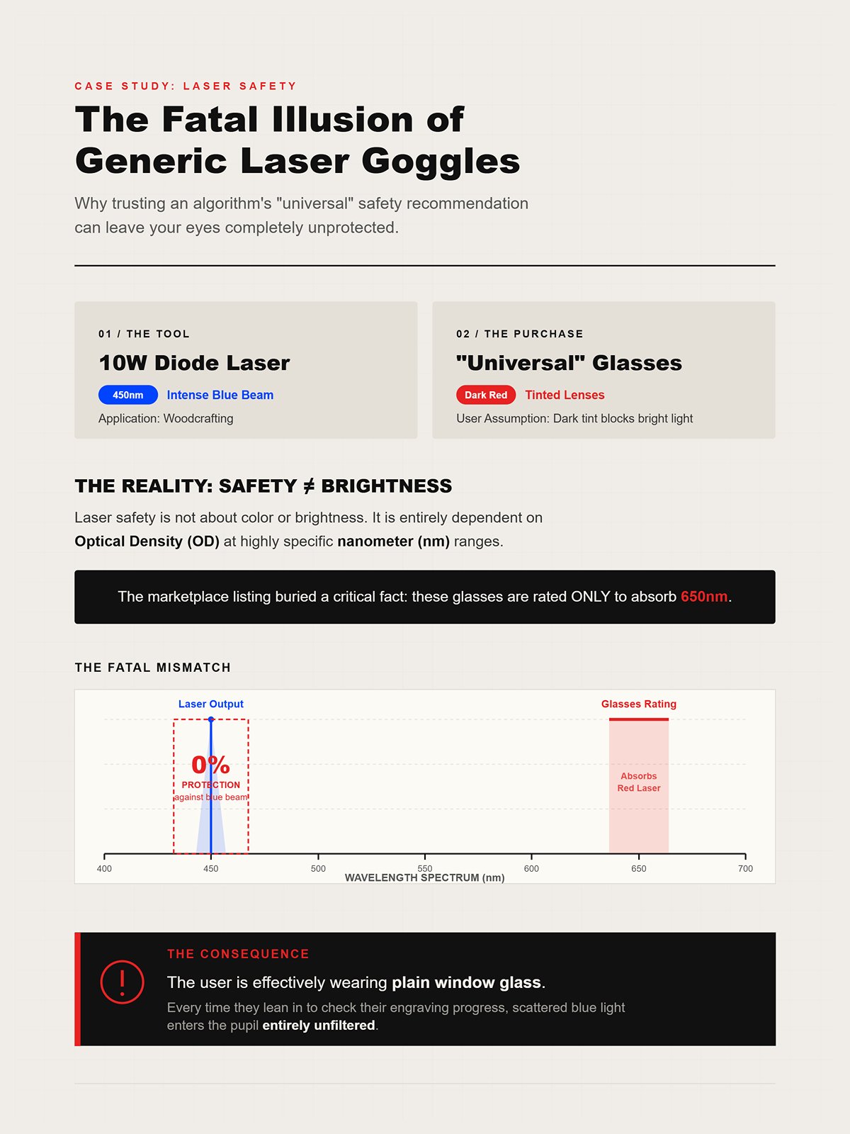
Here is the second expensive mistake I made: assuming a lens was the right tool for the job just because it threaded perfectly into my 20-millimeter focal tube. I bought a cheap zinc selenide replacement online, screwed it in, and wondered why my fine-line vector scoring suddenly looked like it was drawn with a permanent marker.
Mechanical fit is a false proxy for optical performance.
Lenses are physical hand tools. You wouldn’t use a crowbar to pull a splinter, and you wouldn’t use tweezers to pry open a shipping crate. Yet beginners routinely use a standard 2-inch plano-convex lens for every single job, from micro-engraving anodized aluminum to slicing thick MDF. When the lens shape and substrate aren’t matched to the material’s thickness and density, the beam suffers from spherical aberration. The light rays passing through the edges of the lens don’t focus at the exact same point as the rays passing through the center.
How do you know if your perfectly fitting lens is actually scattering your beam?
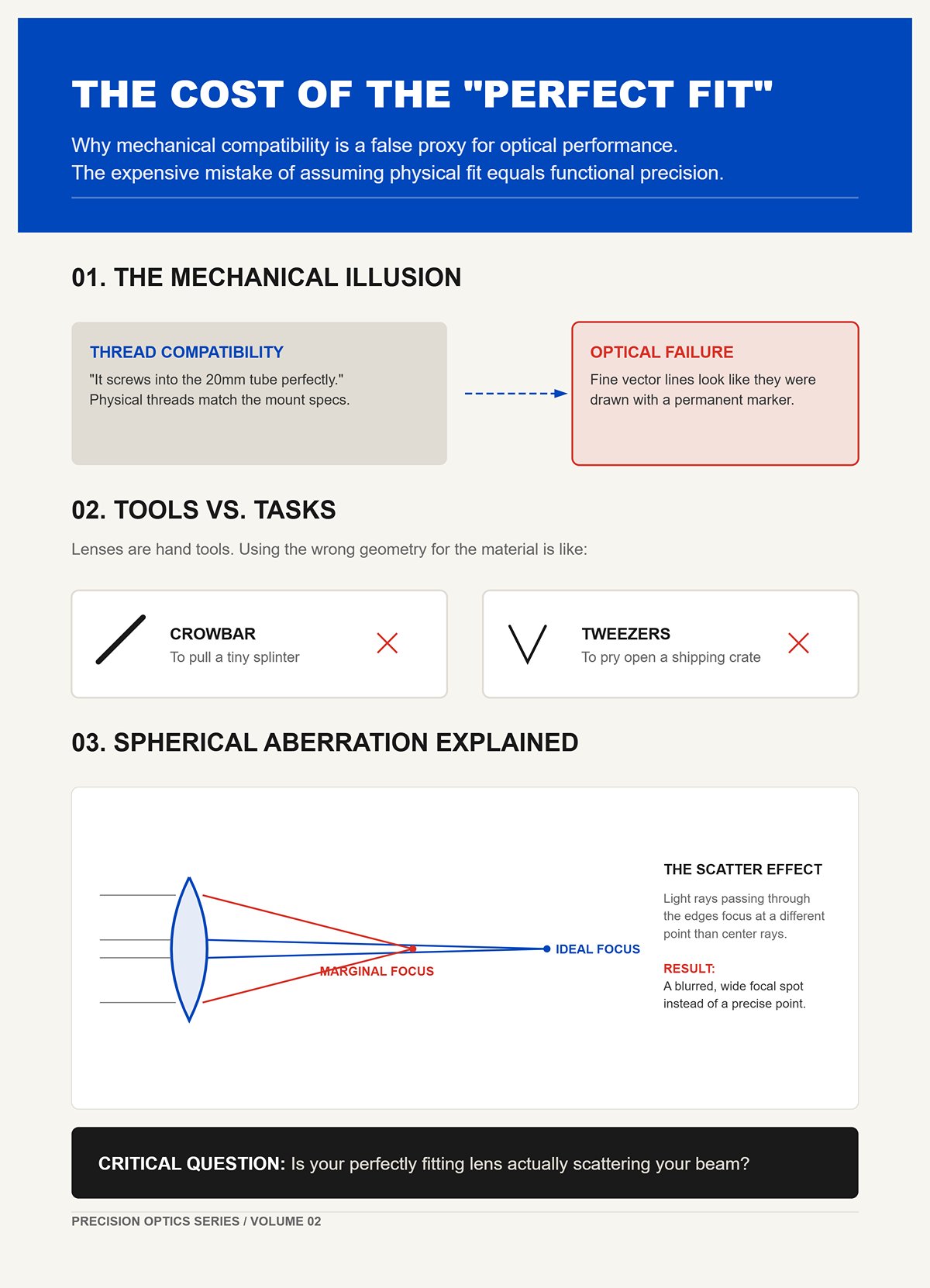
Most beginners picture a laser lens like a magnifying glass burning ants on a sidewalk. They assume that a narrow, tight beam entering the lens will naturally produce a narrow, tight spot on the material. Because of this, when they upgrade to higher-wattage tubes—which physically produce wider-diameter beams—they panic, thinking the wider beam is causing their muddy engravings.
Optical physics works exactly backward.
When a wider, properly collimated beam hits a lens, it actually produces a tighter, higher-quality focal spot than a narrow beam does. Industrial systems use beam expanders early in the optical path specifically to fatten the beam before it reaches the lens. A wider input uses more of the lens’s curvature, creating a steeper convergence angle that punches through material with brutal efficiency.
Before you ever touch the power settings again, you must run the Scrap Bin Test. Take a piece of scrap anodized aluminum, set your laser to its lowest firing power, and pulse it exactly once at the perfect focal distance. Look at the dot under a jeweler’s loupe. If it looks like a crisp pinprick, your optics are dialed. If it looks like a fuzzy, oblong comet, your lens is failing you.
If the lens is the true bottleneck, what happens when we try to force that fuzzy comet deep into a piece of thick hardwood?
In industrial laser testing, dropping a beam’s spot size from a blunt 322 microns down to a needle-like 50 microns does not just make the resulting line thinner. It fundamentally alters the geometry of the melt pool, creating a seven-fold difference in how deep the laser penetrates the material relative to its width. A microscopic change in the beam’s diameter dictates the difference between a shallow surface scratch and a structural, deep-tissue slice. The beam’s geometry controls the cut, and the lens controls the geometry.
How exactly does a curved piece of glass dictate that geometry?
Here is the expensive mistake I made: I thought my focal lens was just a magnifying glass that made the beam smaller. I pictured it taking a straight, thick column of light from the tube and simply shrinking it down to a tiny dot on the wood, like scaling down a photograph on a computer screen. Because I believed the beam stayed straight, I assumed a smaller dot would naturally punch a perfectly straight, microscopic hole all the way through my material.
Optical physics does not shrink light; it bends it into an hourglass.
When the raw beam hits the convex curve of your lens, the light rays are forced inward at an angle. The top half of our optical hourglass is the light converging from the lens down to the focal point—the absolute narrowest part of the beam, which we call the “pinch.” But the light does not stop there. The bottom half of the hourglass is the light diverging, or spreading back out, after it passes that focal point. Think of your focused laser beam like a pair of tweezers: the arms angle inward to a sharp point, but past that point, the geometry reverses.
What happens when you try to force those delicate, sharply angled tweezers through a thick piece of material?
Here is the expensive mistake I made: I bought a short 1.5-inch focal length lens to get the absolute sharpest, smallest spot size possible, then tried to use it to cut half-inch plywood. The top millimeter of the wood looked surgically precise, but the bottom of the cut was a charred, V-shaped canyon that trapped smoke, ruined the edge, and started a small fire in my laser bed.
When you use a short focal length lens, you create a steep, aggressive angle of convergence.
You get a microscopic spot size at the pinch, which is perfect for engraving tiny text. But here is the brutal catch of optical physics: depth of field is exactly twice the Rayleigh range, which is the exact distance from the pinch where the spot diameter doubles. This is not a gradual, forgiving fade. It is a cliff edge. Once you pass that boundary, the beam loses coherence and spreads out violently. Shoving a short-focal beam through thick wood is like shoving those needle-nose tweezers into an oak board—the tips just wedge, spread, and burn the surrounding walls.
Before you ruin another sheet of plywood, run the Scrap Bin Test. Take a thick block of clear scrap acrylic, set your focus perfectly to the top surface, and fire a single continuous pulse while watching from the side. You will physically see the hourglass shape burned into the plastic—a tiny, bright pinch at the top that flares out into a wide, messy, melted cone at the bottom.
If sharp lenses flare out and wide lenses cannot engrave fine details, is there a magical middle ground?
The short answer is no. Spot size is directly proportional to focal length. A shorter focal length mathematically guarantees a tighter focus, but it also guarantees a higher divergence angle past the focal point. You are standing on a physical seesaw. If you push precision up, your depth of field slams down. If you swap to a 4-inch lens to get a long, straight beam path for cutting thick foam, your spot size balloons out. You get a straight edge, but you lose the ability to engrave crisp, high-resolution photographs.
You cannot cheat the seesaw.
This assumes your laser is firing perfectly, which it rarely is. If your beam quality degrades—measured industrially as a higher M² value—it acts as a multiplier on this exact problem. Poor optics do not just blur your engraving; they actively shrink your usable working depth. A dirty or mismatched lens forces that cliff edge to happen even sooner, turning what should be a clean cut into a muddy, heat-warped failure. You have to stop looking for one magical lens to leave in your machine forever. You must treat lenses like drill bits, swapping them out based on the exact thickness and density of the material on your honeycomb bed. This principle of matching the tool to the task is fundamental in all precision fabrication, whether you’re working with laser optics or selecting the right Press Brake Toolings for a specific bending job.
How do you match the exact focal length to the specific material sitting on your workbench?
Here is the expensive mistake I made: I bought a 1.5-inch focal length lens to engrave microscopic serial numbers on a batch of wooden plaques, assuming the tightest possible spot size would guarantee the sharpest possible text. The first plaque, cut from perfectly flat MDF, looked like it was printed with a high-end laser printer. The second plaque, cut from standard 1/8-inch birch plywood, looked like it had been drawn with a melted crayon. I assumed my tube was dying. The truth was much more embarrassing.
A 1.5-inch lens creates a brutally sharp focal pinch, but that precision comes at the cost of your depth of focus.
Depth of focus is the vertical distance where the beam stays tight enough to do useful work. On a 1.5-inch lens, that usable window is barely a millimeter deep. If your material has even a slight natural bow—which almost all hobbyist wood does—the surface of the wood physically rises out of that microscopic sweet spot. The beam spreads out before it even touches the grain, turning your surgical strike into a muddy, unfocused burn. The “high precision” promise of short lenses backfires the moment you introduce real-world, uneven materials.
If the 1.5-inch lens is too fragile for everyday shop materials, is the standard lens that came with your machine the safer bet?
Open the laser head of almost any commercial CO2 machine, and you will find a 2.0-inch lens sitting inside. Manufacturers ship this lens as the factory default because it is the optical equivalent of an adjustable crescent wrench. It has a tight enough spot size to engrave legible text, and a long enough depth of focus to cut through a sheet of quarter-inch acrylic without causing a fire. It is a jack-of-all-trades, and a master of absolutely none.
The 2.0-inch lens shines when you are engraving curved surfaces like rotary tumblers, because its moderate depth of field easily absorbs the slight height variations of a cylinder. But a laser beam is not a hammer, and you cannot force a compromise tool to perform specialized work.
When you try to run high-resolution photo engravings with a 2.0-inch lens, the spot size is physically too large to recreate fine grayscale dots, resulting in washed-out images. When you try to cut half-inch hardwood, the beam diverges too early, scorching the bottom half of the cut. Relying exclusively on your factory 2.0-inch lens means you are artificially capping your machine’s capabilities to the middle of the road.
If the default lens strips the bolt on thick materials, what do you need to cleanly punch through dense stock?
Here is the expensive mistake I made: I tried to cut a sheet of half-inch cast acrylic with my trusty 2.0-inch lens, slowing the machine down to a crawl to force the beam through. The top of the cut was pristine, but the bottom was a melted, V-shaped canyon that welded itself back together before I could even open the lid.
Longer focal lengths—ranging from 2.5 to 4.0 inches—solve this by stretching the optical hourglass. The angle of convergence is much shallower, which means the beam stays relatively straight for a much longer vertical distance. This allows the laser energy to vaporize the bottom of a thick piece of material just as cleanly as the top.
Before you even think about putting a sheet of expensive cast acrylic on the honeycomb bed, you must run the Scrap Bin Test. Fire a test line across a thick scrap piece using your default 2.0-inch lens. If the kerf looks like a V instead of an I, you swap to a 4-inch lens immediately.
But there is a trap hidden in long lenses: they amplify the inherent flaws of your laser tube. If your laser source has poor beam quality—measured industrially as an M² value much larger than 10—the raw beam is already messy and scattered. Imagine trying to power-wash grime off a concrete driveway. Stepping back with a longer wand gives you a wider, straighter spray path, but if your water pressure is garbage to begin with, you just get a gentle mist that doesn’t cut anything. A 4.0-inch lens magnifies a poor M² value over distance, meaning your spot size balloons so badly that the beam loses the power density required to cut.
Focal length solves the depth problem, but even the perfect focal length will fail if the physical shape of the glass distorts the beam.
Here is the expensive mistake I made: I ran a massive batch of edge-to-edge anodized aluminum tags with a standard flat-bottomed plano-convex lens, and every single tag on the outer perimeter came out blurry. I spent hours checking my belts, my mirrors, and my gantry squareness. The mechanicals were flawless. The culprit was the physical shape of the glass, bending the outer edges of my laser beam like a crowbar.
A plano-convex lens—the stock optic in 90% of commercial laser machines—is curved on the top and perfectly flat on the bottom. When the raw, collimated laser beam hits that curved top surface, the light rays near the dead center pass through relatively cleanly. But the rays hitting the outer edges of the curve are forced to bend at a much sharper angle. When all of those rays exit the flat bottom of the lens, they do not meet at a single, microscopic point. Because the outer rays bent harder, they cross the center axis slightly higher up than the inner rays.
This optical slop is called spherical aberration.
Imagine trying to drive a dozen long screws into a dense piece of oak without pilot holes. The screws in the center might go in straight, but the ones on the edges will wander, bite at weird angles, and splinter the wood. Your laser beam is doing the exact same thing when it exits a flat surface. You aren’t getting a pinpoint of light; you are getting a smeared, vertical focal line. The wider your raw laser beam is before it hits the lens, the more of that outer curve it uses, and the worse the spherical aberration becomes. If a flat edge inherently smears the beam, why does the industry still treat it as the default?
Here is the expensive mistake I made trying to fix that exact problem: I spent $150 on a premium II-VI meniscus lens to upgrade a mid-tier DIY laser, only to discover the beam quality actually got worse. A meniscus lens is curved on both sides—convex on top, concave on the bottom, like a rigid contact lens. Because both surfaces are curved, the light rays bend more gradually across two planes instead of violently across one flat exit plane. The outer rays and inner rays converge much closer together, drastically reducing spherical aberration and creating a tighter, crisper spot for high-resolution photo engraving.
But a laser beam is not a magic wand, and it cannot overcome sloppy mechanical housing.
Most hobbyist and light-commercial machines feature aluminum lens tubes machined exclusively to hold flat-bottomed plano-convex lenses. A meniscus lens requires a specific, contoured mounting ledge to accommodate its concave bottom. If you try to drop a meniscus lens into a flat mount, it will not seat flush. It will sit at a microscopic tilt, usually held in place by a retaining ring that applies uneven pressure to the delicate edges of the glass.
A perfectly ground meniscus lens sitting at a one-degree tilt produces a worse beam than a cheap plano-convex lens sitting perfectly flat.
Before you spend a dime upgrading to a meniscus lens, you must run the Scrap Bin Test. Drop a perfectly flat, rigid metal washer into your bare lens tube and tap the side of the housing with a screwdriver handle. If the washer rattles, shifts, or sits unevenly, your machine’s tolerances cannot handle the upgrade. You will just be paying a premium to misalign your optics. If meniscus lenses are this finicky, does that mean the “sloppy” plano-convex lens actually has a hidden advantage?
We just spent two sections treating spherical aberration like a disease, but in high-power cutting, a surgically tight focal spot is actually a liability. If you focus 130 watts of power into a microscopic dot to cut thick plywood, the top of the material vaporizes instantly, but the beam crosses its focal point and diverges so rapidly that it loses the power density needed to punch through the bottom. Imagine trying to drill a deep, straight hole with a wide countersink bit instead of a long auger. You just end up excavating a shallow crater.
This is the spherical aberration trap: assuming optical perfection always equals workshop performance.
Because a plano-convex lens naturally suffers from spherical aberration, that “smeared” focal line we complained about earlier becomes a massive asset for cutting. It creates a longer effective focal zone. The beam stays hot and narrow over a longer vertical distance. Some veteran operators will even install a plano-convex lens upside down—flat side facing the incoming beam—to intentionally maximize this aberration. The light stumbles through the glass, extending the focal pinch into a long, vertical column of heat. You entirely lose the ability to engrave fine text, but you gain the brute force required to slice through half-inch acrylic without the dreaded V-shaped kerf.
Lens shape dictates how the beam bends to achieve that cut, but the physical glass substrate dictates how much heat and debris the optic can survive before it shatters in the middle of a job.
Here is the expensive mistake I made when I first started running high-volume MDF jobs: I kept buying standard Zinc Selenide (ZnSe) lenses because the spec sheets promised they transmit 99% of a CO2 laser’s light. I was obsessing over optical purity while ignoring the physical reality of my shop. When you cut manufactured woods, the vaporized glue turns into a thick, yellow resin smoke. ZnSe is a brittle, crystalline salt with terrible thermal conductivity. When that sticky resin settles on a ZnSe lens, the dirt blocks the light, the light turns into heat, and the glass cannot shed that heat fast enough. The center of the lens expands while the edges stay cool, and the optic cracks right down the middle.
If ZnSe is so fragile, why is it the industry standard? Because in a sterile laboratory environment, it is optically flawless. But a laser beam is not a hammer. You cannot just force it through a dirty window by turning up the wattage.
When I finally switched to Gallium Arsenide (GaAs), my lens replacement budget dropped by 80%. GaAs is a dark, metallic-looking semiconductor. It only transmits about 93% of the beam, which looks like a downgrade on paper. But GaAs is physically tougher and conducts heat far better than ZnSe. When resin coats a GaAs lens, the heat spreads evenly across the entire substrate instead of pooling in the center. It survives the thermal shock of a dirty workspace simply because it refuses to trap the heat.
| Aspect | Zinc Selenide (ZnSe) | Gallium Arsenide (GaAs) |
|---|---|---|
| Optical Transmission | ~99% transmission of CO₂ laser light | ~93% transmission of CO₂ laser light |
| Material Type | Brittle, crystalline salt | Dark, metallic-looking semiconductor |
| Thermal Conductivity | Poor; cannot dissipate heat efficiently | Good; spreads heat evenly across substrate |
| Durability in Dirty Workspace | Fragile; prone to cracking under thermal stress | Physically tougher; resists thermal shock |
| Reaction to Resin Smoke | Resin blocks light, heat builds at center, lens cracks | Heat disperses evenly, reducing risk of cracking |
| Performance in Sterile Environment | Optically flawless; industry standard | Slightly lower transmission but still effective |
| Real-World MDF Shop Performance | High failure rate; frequent replacements | 80% reduction in replacement costs |
| Key Weakness | Traps heat when contaminated | Slightly lower optical transmission |
| Key Strength | Maximum optical purity | Superior durability and heat management |
Bare ZnSe naturally reflects about 14.5% of the laser energy hitting its surface. If you bounce 100 watts off a bare lens, 14.5 watts never make it to the material. To fix this, manufacturers apply microscopic layers of dielectric Anti-Reflective (AR) coating to the top and bottom of the lens. These coatings use destructive interference to cancel out the reflections, forcing 99% of the light through the glass.
But these invisible layers are incredibly delicate. Imagine trying to power-wash grime off a concrete driveway while wearing silk socks. The concrete—the substrate—can handle the pressure, but the silk—the coating—will shred instantly if subjected to friction or trapped heat.
When soot and vaporized acrylic stick to the AR coating, they act like a black t-shirt in the July sun. The dirt absorbs the laser’s energy, instantly spiking the surface temperature. Because the AR coating is structurally different from the ZnSe substrate beneath it, the two materials expand at drastically different rates when heated. This mismatch creates massive mechanical stress. The coating doesn’t just get hot; it physically shears itself away from the glass. This is thermal runaway. The more the coating degrades, the more laser energy it absorbs, which generates more heat, accelerating the destruction until the lens shatters.
Here is the expensive mistake I made misdiagnosing thermal runaway: I assumed my tube was dying because my cuts were suddenly taking three passes instead of one. I pulled the lens, saw a cloudy brown smudge right in the dead center, and scrubbed it aggressively with acetone and a cotton swab. The brown smudge didn’t budge. I scrubbed harder, thinking it was baked-on pine sap. I was actually trying to scrub away a crater.
When an AR coating melts, it leaves a permanent, cloudy scar that looks exactly like a stubborn smoke stain. But if you drag a pristine cotton swab across a melted coating, you will feel a microscopic drag—like pulling a rag across fine sandpaper. That is the physical texture of a destroyed dielectric layer. No amount of chemical solvent will fix it, because the material is simply gone.
Before you waste hours chasing electrical gremlins or realigning your mirrors, you must run the Scrap Bin Test. Take a piece of scrap cast acrylic—at least half an inch thick—and fire a single, stationary pulse at 50% power for two seconds. Look at the shape of the vaporized cavity. A healthy AR coating and substrate will produce a deep, perfectly symmetrical cone. A melted AR coating scatters the beam wildly, producing a shallow, lopsided crater that looks like a spoon scooped out the plastic. If your test yields a shallow crater, your lens is already dead.
For my first three years in this business, I treated my laser’s focal lens like a permanent fixture of the machine. I bolted a standard 2-inch plano-convex lens into the carriage and expected it to flawlessly engrave anodized aluminum in the morning and slice through half-inch plywood in the afternoon. When the plywood inevitably charred or the engraving looked blurry, I did what every frustrated rookie does: I cranked up the wattage and slowed down the gantry. But a laser beam is not a hammer. You cannot bully your way through dense material by simply applying more brute force to a mismatched tool.
If you treat your optics like interchangeable drill bits instead of precision instruments, you will continue to bleed money into your scrap pile. The mount on your laser head only exists to hold the glass; it is the physical material on your honeycomb bed that dictates exactly which piece of glass belongs in that mount. To stop ruining expensive substrates, you have to stop guessing and start selecting your optics based on the exact bottleneck of the job in front of you. How do you decide which variable matters most?
Every job forces you to choose a priority, and your lens must match that choice. If you are optimizing for fine detail—like engraving 4-point text on a rubber stamp—you need a short focal length lens (like 1.5 inches). This acts like a fine-tipped needle, concentrating the beam into a microscopic dot. But that needle-point diverges rapidly, meaning it loses its cutting power the moment it penetrates the surface. If you try to cut thick acrylic with that same detail-oriented lens, the beam widens into a V-shape, melting the edges instead of slicing them.
When thickness is your priority, you must switch to a longer focal length (like 3 or 4 inches). This acts like a long, straight crowbar, keeping the beam relatively parallel deep into the cut. But there is a hidden physics trap here: standard plano-convex lenses naturally introduce spherical aberration. Because the curved glass bends light differently at its edges than at its center, it creates quartic phase distortions. In workshop terms, it acts like a warped magnifying glass, degrading your beam quality factor (M²) and turning your sharp focal point into a messy, elongated blur. To fix this, you often have to intentionally defocus the beam slightly to find the sweet spot.
High-speed cutting introduces an entirely different bottleneck: heat. If you are pushing maximum wattage to cut fast, the thermal load can physically warp the laser crystal or the mirrors before the light even reaches your lens. This thermal distortion scrambles the beam inside the tube. If your beam is already mangled by heat before it hits the carriage, swapping to a pristine lens will not save your cut. So, if the optics are matched perfectly to the job but the cuts are still failing, where is the invisible flaw hiding?
Here is the expensive mistake I made when I tried to stretch the lifespan of my optics: I assumed my tube was dying because my beam was suddenly losing 30% of its cutting power. I spent a week checking water chillers and high-voltage power supplies, completely ignoring the microscopic condition of my lens. I had been wiping the lens daily with dry cotton swabs, unknowingly dragging tiny particles of vaporized metal across the glass. I had turned my cleaning routine into a daily sanding session.
Micro-scratches are invisible under normal shop lighting, but they act like thousands of tiny speed bumps and prisms. When the laser hits those scratches, the light scatters wildly, creating parasitic reflections that bounce around inside the air assist nozzle instead of focusing onto your material. To catch this, you must perform the Flashlight Test. Pull the lens out of the machine, take it into a dark room, and shine a harsh LED flashlight directly across the surface of the glass at a steep, horizontal angle. If the lens is healthy, the light will pass over it invisibly. If it is damaged, the micro-scratches will catch the LED light and illuminate like a spiderweb of glowing canyons.
Before you load a sheet of expensive material, you must mandate the Scrap Bin Test.
Take a scrap block of clear, thick acrylic, place it under the laser, and fire a single, low-power pulse for two seconds. Look closely at the physical shape of the frosted burn cone inside the plastic. If the cone is a perfectly symmetrical, sharp dagger, your lens is focusing correctly. If the cone is lopsided, leaning to one side, or surrounded by a hazy cloud of secondary burns, your lens is actively scattering light and must be replaced immediately. But if we know a dirty lens ruins cuts, why is aggressively cleaning it sometimes the exact thing that destroys it?
Here is the expensive mistake I made trying to chase perfect optical clarity: I noticed a stubborn ring of hazy residue on a brand-new lens, so I soaked a wipe in pure acetone and scrubbed the glass with heavy thumb pressure until the haze disappeared. I put the lens back in the machine, fired a test cut, and watched the optic instantly shatter into three pieces. I hadn’t cleaned off residue; I had forcefully stripped away the anti-reflective (AR) coating, leaving the raw substrate exposed to absorb massive amounts of heat.
Imagine trying to power-wash grime off a concrete driveway while wearing silk socks. The concrete—the thick lens substrate—can handle the immense pressure and heat of the laser beam. But the silk socks—the microscopic layers of dielectric AR coating—will shred instantly if subjected to friction.
When you scrub a lens with pressure, you are physically tearing that delicate interference layer off the glass. Once that coating is compromised, the lens begins reflecting its own laser energy inward, creating localized hot spots that lead to catastrophic thermal runaway. The secret to optical longevity is accepting that a functional lens does not need to look like a polished diamond. You use a solvent to float the debris off the surface, and you use a lens tissue to gently wick the moisture away without ever applying downward pressure. When you stop treating your optics like dirty windshields and start treating them like the fragile, mathematical instruments they are, your scrap bin will finally stay empty. For more insights on precision tooling and maintenance across different fabrication technologies, explore the resources available from Jeelix, a leader in providing solutions for demanding manufacturing environments. You can also download our comprehensive Brochures for detailed product information and technical specifications.
 العربية
 বাংলা
বাংলা
 Български
 Čeština
 Dansk
Dansk
 Nederlands
 Suomi
Suomi
 Français
 Deutsch
 Ελληνικά
 עִבְרִית
 हिन्दी
 Magyar
 Bahasa Indonesia
 Italiano
 日本語
日本語
 Қазақ тілі
 한국어
한국어
 Bahasa Melayu
 Norsk bokmål
 فارسی
فارسی
 Polski
 Português
 Română
 Русский
 Српски језик
 Slovenčina
 Español de México
 Español
 Kiswahili
 Svenska
 Tagalog
 தமிழ்
தமிழ்
 ไทย
ไทย
 Türkçe
 Українська
 اردو
اردو
 Tiếng Việt
 简体中文
简体中文
 香港中文
香港中文
 繁體中文
繁體中文