Showing all 6 results
Standard Press Brake Tooling, Press Brake Punch
Standard Press Brake Tooling, Press Brake Punch
Standard Press Brake Tooling, Press Brake Punch
Standard Press Brake Tooling, Press Brake Punch
Standard Press Brake Tooling, Press Brake Punch
Standard Press Brake Tooling, Press Brake Punch
Take a walk past the scrap bin in any mid-sized fabrication shop. You’ll see the same scene every time: half-formed boxes, crushed return flanges, and warped brackets that look like they went a few rounds with a hydraulic press—and lost.
Ask the operator what went wrong, and the brake gets the blame. Or the material thickness. Or the engineer who designed the flat pattern. Almost never does anyone point to the solid block of steel bolted into the ram.
Because it’s the “standard” punch, it’s treated as the default. And “standard,” in many minds, automatically means “universal.”
If you’re relying exclusively on one profile from your rack of Press Brake Toolings, you may already be paying for that assumption in scrap, downtime, and fractured tooling.
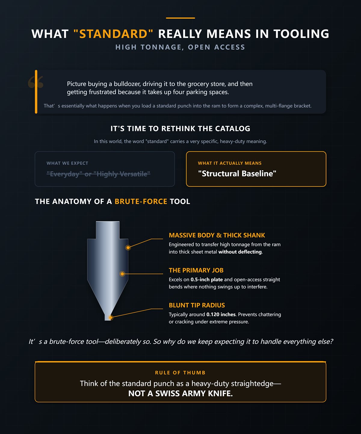
Picture buying a bulldozer, driving it to the grocery store, and then getting frustrated because it takes up four parking spaces. That’s essentially what happens when you load a standard punch into the ram to form a complex, multi-flange bracket.
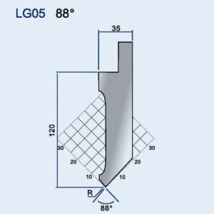
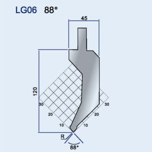
It’s time to rethink how we read tooling catalogs. In this world, “standard” doesn’t mean “everyday” or “highly versatile.” It means “structural baseline.” A standard straight punch features a massive body, a thick shank, and a relatively blunt tip radius—typically around 0.120 inches. It’s engineered for one primary job: transferring high tonnage from the ram into thick sheet metal without deflecting, chattering, or cracking. It excels on 0.5-inch plate. It performs beautifully on open-access straight bends where nothing swings up to interfere.
It’s a brute-force tool—deliberately so. So why do we keep expecting it to handle everything else?
Rule of thumb: Think of the standard punch as a heavy-duty straightedge—not a Swiss Army knife.
If you’re evaluating baseline options, reviewing a full range of Standard Press Brake Tooling profiles can quickly reveal just how application-specific “standard” really is.
Take a close look at the geometry of a standard punch profile. You’ll notice a thick, flat outer face with only minimal concave relief.
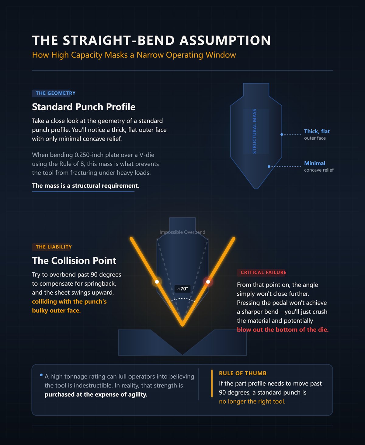
When you’re bending 0.250-inch plate over a V-die using the Rule of 8 (with a V-opening eight times the material thickness), that thick outer face is precisely what prevents the tool from fracturing under heavy, off-center loads. The mass is a structural requirement. But that same mass becomes an immediate liability the moment your bend angle tightens. Try to overbend past 90 degrees to compensate for springback, and the sheet swings upward, colliding with the punch’s bulky outer face at roughly 70 degrees. From that point on, the angle simply won’t close further. If you keep pressing the pedal, you won’t achieve a sharper bend—you’ll just crush the material against the punch and potentially blow out the bottom of the die.
A high tonnage rating can lull operators into believing the tool is indestructible. In reality, that strength is purchased at the expense of agility, confining you to a narrow range of shallow, unobstructed bends. So how do operators work around this physical limitation?
Rule of thumb: If the part profile needs to move past 90 degrees, a standard punch is no longer the right tool.
Not long ago, I watched a second-year apprentice attempt to form a deep, four-sided box with return flanges using a standard straight punch.
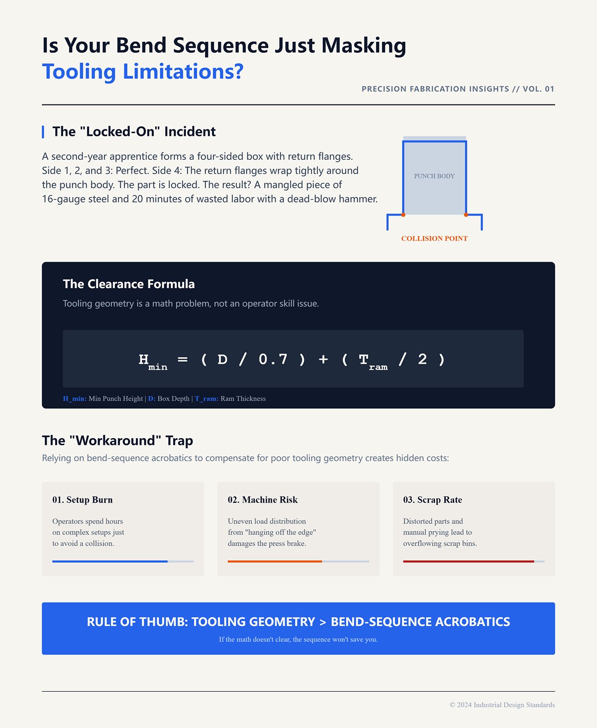
He bent sides one, two, and three without issue. On the final bend, however, the return flanges rotated upward and wrapped tightly around the punch’s bulky body. When the ram retracted, the box lifted with it—locked onto the tool. He spent twenty minutes prying a mangled piece of 16-gauge steel off a $1,500 punch with a dead-blow hammer. That scrapped part wasn’t the machine’s fault, nor was it operator clumsiness. It was a math problem. For a box with return flanges, the minimum punch height should equal the box depth divided by 0.7, plus half the ram thickness. Without that clearance, the part will trap itself.
Rather than investing in a taller, relieved punch or a gooseneck, many shops resort to extreme workarounds. Operators will hang a three-sided box halfway off the edge of the brake for the final bend just to avoid a collision. They burn hours on setup, risk uneven load distribution that can damage the machine, and fill scrap bins with distorted parts—all to avoid acknowledging that their so-called “do-everything” punch simply isn’t designed for this job. In many cases, a properly selected relieved or custom profile from a line of Special Press Brake Tooling would eliminate the workaround entirely.
Rule of thumb: Don’t rely on bend-sequence acrobatics to compensate for a tooling geometry issue.
Take a close look at a standard punch sitting on the tooling rack. At first glance, it seems straightforward—a wedge of hardened steel tapering to a blunt edge. But that geometry is anything but random. It embodies a strict mathematical balance between force, surface area, and clearance.
Think of it like a bulldozer. A bulldozer is brilliantly engineered to push enormous loads in a straight line, yet it will destroy everything around it if you try to squeeze it into a tight parallel parking spot. That is precisely what happens when you mount a standard punch in the ram to form a complex, multi-flange bracket. You are asking a tool designed for one set of physics to perform in a completely different scenario. You are ignoring the math—and the math always wins. So where, exactly, does this internal geometry start working against us?
Grab a pair of calipers and measure the tip radius on the standard punch you use for most jobs. Chances are it is a sharp 0.040 inches. Now compare that to the 0.250-inch mild steel plate you are preparing to bend.
Air bending works because the material spans the V-die opening while the punch tip presses downward to form the inside radius. But when the punch tip radius is dramatically smaller than the material thickness, the process changes. The tool is no longer bending the metal—it is driving into it.
Last year, I was called into a shop after an operator attempted to force a 0.500-inch steel plate into a tight V-die using a standard acute punch with a 0.040-inch radius. He assumed the sharp tip would produce a crisp inside corner. Instead, the moment the ram reached the pinch point, that tiny radius focused 100 tons of force onto an almost microscopic contact area. It pierced the zinc-rich surface and unintentionally coined the material.
The pressure skyrocketed. The metal had nowhere to displace. And a $2,000 die fractured straight down the center with a gunshot-like crack that sent fragments into the ceiling. The scrapped part—and the ruined tooling—were the predictable consequences of ignoring the relationship between tip radius and material thickness.
Physics is not negotiable. If thicker material demands higher tonnage, you must move to a straight punch with a larger radius—say, 0.120 inches—to spread the load properly. But what happens when we correct the radius and overlook the included angle?
Rule of thumb: Never allow your punch tip radius to drop below 60 percent of the material thickness—unless your goal is to split your die in two.
Every sheet metal part pushes back. When you form a 90-degree flange, the material’s natural elasticity causes it to spring open the instant the ram retracts. To achieve a true 90-degree angle, you must overbend to 88—or even 85—degrees. That’s where your punch’s included angle becomes a matter of survival.
A standard straight punch typically features an 85- or 90-degree included angle. It’s thick. It’s rigid. When forming materials with significant springback—such as high-strength steels or certain aluminum alloys—you may need to drive the bend down to 80 degrees. The moment you attempt that with a standard 85-degree punch, the sheet metal collides with the punch’s sidewalls.
The ram continues downward, but the angle stops closing.
This is precisely why acute punches exist. With included angles ranging from 25 to 60 degrees, they provide the clearance needed to overbend without interference. But here’s the catch that traps many apprentices: narrowing the angle weakens the tool. An acute punch with a 0.4 mm tip may be rated for only 70 tons per meter, while a robust standard punch can withstand well over 100 tons. You’re trading structural strength for geometric flexibility. The real question is: how do you know when you’ve given up too much?
Rule of thumb: Choose your included angle based on the required overbend—not the final angle on the part drawing.
Tooling catalogs display tonnage limits in bold for a reason—yet many operators treat them as rough guidelines. A standard straight punch earns its high tonnage rating—often exceeding 100 tons per meter—because of its vertical mass. The load travels straight up through the shank into the ram. The design is mathematically optimized for pure vertical compression.
Complex geometries, however, demand more than vertical force—they introduce lateral stress. When forming an asymmetrical profile or using a narrow V-die to squeeze out a short flange, the material reacts unevenly. The tonnage doesn’t just push upward; it pushes sideways. Standard punches are not engineered to absorb significant lateral deflection. If you force a standard punch into a high-tonnage, acute bend with a tight die opening, you’re no longer simply bending metal—you’re applying shear stress to the tool’s neck. The punch’s impressive vertical capacity masks this risk, creating a false sense of security right up to the moment it permanently deflects.
You are not merely exceeding the tool’s rated capacity; you are loading it in a direction it was never designed to endure. The internal geometry of a standard punch is engineered for rigidity under pure vertical compression. But how does that carefully calculated vertical strength turn into a real-world crash the moment the workpiece begins to rotate upward?
Rule of thumb: Respect the vertical tonnage rating—but be wary of lateral deflection.
Install a standard straight punch with a 4-inch profile height in your press brake, then attempt to bend a 6-inch leg on a simple 90-degree bracket. As the punch forces the material into the V-die, the 6-inch leg swings upward like a door closing. At roughly 120 degrees of rotation, the sheet edge collides squarely with the heavy steel ram that holds the tooling. The bend is physically blocked. There is no workaround for this geometry.
A standard punch is like a bulldozer—excellent at pushing immense loads in a straight line, but guaranteed to cause damage if you try to maneuver it into tight, complex geometry. It simply does not provide the vertical clearance required for deep flanges. The math is unforgiving: your maximum flange length is limited by the punch height plus the daylight opening of your clamping system. Ignore that constraint and force the ram downward anyway, and the machine will not conjure extra clearance. It will drive the workpiece edge straight into the clamping hardware, bowing the sheet outward and ruining the flange’s straightness.
Rule of thumb: Never program a flange longer than the punch’s vertical profile height—unless the bend is directed away from the machine.
Examine the cross-section of a standard punch. It drops straight down from the tang, then widens into a thick, load-bearing belly before tapering to the tip. Now imagine forming a U-channel with a 2-inch base and 3-inch return flanges. The first bend goes smoothly. You flip the part to make the second bend. As the 3-inch return flange rotates upward toward its final 90 degrees, it sweeps directly into that protruding belly.
Three months ago, an apprentice attempted to form a 4-inch-deep NEMA enclosure using a standard punch. He completed three sides without incident. On the final bend, the opposing return flange rotated upward, met the thick body of the punch at roughly 45 degrees—and he kept his foot on the pedal. The press didn’t stall. It simply forced the return flange into the punch body, warping the entire enclosure into a crushed parallelogram. The instant that flange collides with the broad belly of a standard punch, you’ve turned a $500 component into a piece of abstract art. That’s exactly what happens when you load a standard punch into the ram to form a complex, multi-flange bracket. You’re using a tool designed for open-access bends as if it were a universal skeleton key.
Rule of thumb: If the internal width of your profile is narrower than the widest section of your punch body, the part will crash before it ever reaches 90 degrees.
Walk over to your tooling rack and examine the sides of your oldest standard punches. Don’t focus on the tip. Look about two inches up the shank. You’ll likely see bright, galled streaks—transferred metal smeared into the hardened steel. Those aren’t harmless polishing marks. They’re physical proof of a clearance problem that someone chose to overlook.
When a return flange barely clears the punch, it scrapes along the tool’s side as the bend closes. The operator assumes everything is fine because the finished part still reads 90 degrees. But in reality, raw sheet metal is being dragged across hardened steel under extreme lateral pressure. That friction causes galling, depositing zinc or aluminum directly onto the punch surface. Over time, this microscopic buildup effectively increases the punch width, distorting bend allowances and scoring the inside face of every subsequent part. When the bend angle eventually drifts two degrees out of tolerance, material thickness gets the blame. The real offender is the galled punch. The standard profile was engineered for straight, open bends—so why do we keep demanding that it do everything else?
Rule of thumb: If the sides of your punch are shiny or galled, you’re no longer bending metal—you’re scraping it.
I’ve watched shop owners hesitate over a $400 specialized punch while standing in front of a scrap bin filled with $800 worth of crushed U-channels. They treat specialized tooling like heated leather seats in a work truck—nice in theory, but hardly essential. That’s exactly the mindset at play when you load a standard punch into the ram to form a complex, multi-flange bracket. You’re dismissing the physical reality of the space your metal must occupy.
f you regularly form channels, boxes, hems, or Z-bends, expanding beyond basic Standard Press Brake Tooling into application-specific profiles is not optional—it’s structural risk management.
Take a close look at a gooseneck punch profile. That pronounced undercut—the “throat”—isn’t there for looks. Its sole purpose is to provide clearance for a returning flange when forming deep channels or box shapes. A standard punch blocks that swing; a gooseneck gets out of the way.
But that clearance comes at a steep mechanical cost. When you remove material from the center of a steel tool, you alter the load path. A standard punch transmits force straight down its vertical axis. A gooseneck forces that tonnage to travel around a curve, introducing transverse torsion and increasing the lever arm through the neck.
The very geometry that protects your part is the same geometry that puts your tool at risk.
Last November, a second-year apprentice finally realized he needed a gooseneck to clear a 4-inch return flange on a heavy-equipment chassis. He installed a deep-throat gooseneck, positioned a piece of 1/4-inch A36 steel, and hit the pedal. The flange cleared flawlessly—right up until the 30-ton load snapped the punch at the neck, sending a ten-pound chunk of hardened steel ricocheting off the light curtains. He solved the clearance issue but ignored the tonnage limit. Goosenecks are essential for deep return flanges, yet their maximum load capacity is only a fraction of that of a standard straight punch.
Rule of thumb: If you’re using a gooseneck, calculate the required tonnage first. The relieved throat that saves your part can easily fail under heavy-plate loads.
Try forming a teardrop hem with a standard 90-degree or 85-degree punch. You’ll bottom out in the V-die, blunt the tip of your tool, and the metal will still spring back to 92 degrees. You simply cannot fold metal flat onto itself without first pushing it well past 30 degrees.
This operation requires an acute punch—ground to a sharp 26- or 28-degree knife edge. It penetrates deep into an acute V-die, forcing the sheet metal into a tight, sharply defined V. After establishing that acute angle, you must use a flattening punch or a dedicated hemming die to close the fold completely. Operators who try to shortcut the process by over-stroking a standard punch into a narrow die don’t create a true fold—they roll the material. The standard punch profile is simply too wide to reach the bottom of an acute die without binding against the die walls.
When the hem inevitably springs open in assembly, the blame usually falls on material thickness. In reality, the material was never the issue—the tooling geometry was physically incapable of achieving the required pre-bend angle.
Rule of thumb: Never attempt a hem without a dedicated acute punch to establish the 30-degree pre-bend. Otherwise, you’ll end up coining the material and damaging your die.
Picture forming a half-inch Z-bend along the edge of a two-foot panel. With standard tooling, you make the first bend, flip the heavy sheet, and then attempt to back-gauge off a narrow, angled half-inch flange. The part wobbles, the gauge slips, and your parallel tolerance disappears. Standard punch profiles were designed for straight, open bends—so why keep forcing them to handle operations they weren’t built for?
An offset punch-and-die set forms both opposing bends in a single stroke. The punch face is machined with a step that matches a corresponding step in the die. As the ram descends, the metal is shaped into a precise Z-profile without ever leaving the flat reference plane of the backgauge. You eliminate the flip, remove gauging error, and ensure both flanges remain perfectly parallel.
This isn’t a luxury upgrade for efficiency—it’s a geometric necessity. When the offset distance between bends is smaller than the width of a standard V-die, an offset tool is the only viable way to form the feature. A conventional punch would simply crush the first bend while attempting to create the second.
Rule of thumb: If the center web of your Z-bend is narrower than your standard V-die opening, stop flipping the part and install an offset tool.
| Tool Type | Primary Purpose | Key Mechanical Consideration | Common Failure/Risk | Rule of Thumb |
|---|---|---|---|---|
| Gooseneck Punches | Provide throat clearance for deep return flanges, channels, and box shapes | Undercut throat alters load path; force travels around a curve, increasing torsion and lever arm stress at the neck | Neck fracture under excessive tonnage; significantly lower load capacity than standard straight punches | Always calculate required tonnage before use; goosenecks handle far less load than standard punches |
| Acute & Flattening Punches | Create hems and sharp pre-bends before flattening | Acute punch (26°–28°) forces metal into tight V; standard punches too wide to reach acute die bottom without binding | Springback, rolled material instead of true fold, die damage from over-stroking standard punch | Never attempt a hem without a dedicated acute punch to achieve ~30° pre-bend before flattening |
| Offset Punches | Form Z-bends in a single setup without flipping the part | Stepped punch and die form opposing bends simultaneously while maintaining flat backgauge reference | Loss of parallelism, gauging errors, or crushing first bend when using standard tooling | If Z-bend center web is narrower than standard V-die opening, use an offset tool instead of flipping the part |
You’ve just invested in a 220-ton press brake. You load a heavy plate, set the backgauge for a one-meter bend, and assume the full 220 tons are at your command. They aren’t. If you’re running a standard Promecam punch holder system, the 13 mm-wide intermediate tang has a hard physical limit of 100 tons per meter. Try forcing your machine’s full rated capacity through that narrow section on a one-meter part, and the punch holder will permanently deform long before the ram bottoms out.
The tonnage printed on the machine is a theoretical ceiling. Your tooling is the real constraint.
We often treat the standard straight punch like a bulldozer—ideal for pushing massive loads in a straight line. But drive a bulldozer onto a wooden bridge and it becomes a liability. The standard punch’s tonnage advantage only holds when material properties, sheet thickness, and tool contact length are perfectly matched to support the load. If even one of those variables is off, that supposedly “universal” punch can be the very reason your setup fails.
Air-bending force charts can be misleading. They provide a neat, precise tonnage figure for mild steel—then tack on a casual footnote suggesting you multiply it by 1.5 for stainless.
But Type 304 stainless steel doesn’t just demand more force—it changes its properties as you bend it. The material begins work-hardening the instant the punch tip makes contact. By mid-stroke, the yield strength at the inner radius has already climbed. If you’re using a standard punch with a tight tip radius, that concentrated load has nowhere to dissipate. Instead, it digs into the hardened surface, forming a sharp crease rather than a smooth radius and dramatically increasing the tonnage required to complete the bend. At that point, you’re no longer air bending—you’re coining.
Aluminum presents the opposite kind of trap.
Press a standard punch with a tight radius into 5052 aluminum, and you can exceed the material’s tensile limits on the outer surface before the bend is complete. The sheet may crack along the grain. The standard punch profile assumes the material will flow predictably around the tip. When the material resists—by hardening like stainless or fracturing like aluminum—that generic geometry turns from an advantage into a liability.
Rule of thumb: Never rely on a generic multiplier for stainless steel. Instead, calculate the specific alloy’s tensile strength in relation to your punch tip radius before you ever step on the pedal.
| Material | Behavior During Bending | Risk with Standard Tight Punch | Key Impact on Bend Profile |
|---|---|---|---|
| Mild Steel | Predictable behavior during air bending; follows standard tonnage charts | Generally performs as expected with standard punch geometry | Tonnage values from charts are typically accurate |
| Stainless Steel (Type 304) | Work-hardens immediately upon contact; yield strength increases during the stroke | Concentrated load from tight punch tip creates sharp crease instead of smooth radius; dramatically increases tonnage | Can shift from air bending to coining; generic 1.5× tonnage multiplier is unreliable |
| Aluminum (5052) | Lower tensile limits; prone to cracking, especially along the grain | Tight punch radius can exceed tensile strength before bend is complete, causing outer-surface cracking | Standard punch geometry may cause fracture instead of controlled material flow |
The math behind sheet metal forming is unforgiving: required tonnage increases with the square of the material thickness. Bending 1/4-inch A36 steel over a 2-inch V-die requires about 20 tons per foot. Increase the thickness to 1/2-inch, and the tonnage doesn’t merely double—it quadruples.
This is the point where the standard punch stops being an awkward compromise for complex geometries and becomes an essential, irreplaceable workhorse.
I once saw someone attempt to form 3/8-inch AR400 wear plate using a relieved-throat gooseneck punch because he didn’t want to change setups after running a batch of deep boxes. He assumed that since the press brake was rated for 150 tons, it would handle the job. It did—right up until the punch catastrophically failed. Under 120 tons of pressure, it shattered, driving a jagged fragment of hardened steel into the controller screen and turning a $400 sheet of armor plate into a lasting monument to a bad decision.
Specialized punches simply lack the vertical mass required to withstand 80 tons per foot. They will fracture. Once you exceed the 1/4-inch thickness threshold, concerns about clearing return flanges or forming tight Z-bends become secondary. At that point, you are contending with fundamental physics. The standard straight punch—with its direct vertical load path and thick web—is the only geometry robust enough to survive the squared tonnage demands of bending thick stock.
Rule of thumb: When material thickness exceeds 1/4 inch, retire the specialized tooling and switch to a standard straight punch. Clearance geometry is irrelevant if the tool fails catastrophically.
Go to your tooling rack and examine the side of your standard punch. You’ll find a rating stamped into the steel—something like “100 kN/m.” That figure represents kilonewtons per meter, and it is a strict, non-negotiable limit based on the tool’s contact length.
Shops ignore this all the time. They look at a 6-inch-wide bracket made from 1/4-inch stainless steel, glance at their 100-ton press brake, and assume they are operating safely. But if your standard punch is rated at 40 tons per meter, a 6-inch (0.15 meter) section of that punch can safely transmit only 6 tons of force. If the bracket requires 15 tons to form, the machine will deliver it without hesitation—and the punch tip will collapse under the concentrated load.
That is precisely how you crack a die or permanently deform a punch tip.
A standard punch is strong only when the load is distributed along its length. When you form short, narrow parts that demand high tonnage, the machine’s overall capacity becomes irrelevant. You are channeling the entire force requirement through a tiny contact area. The punch may carry an impressive total rating, but at the exact point of contact, it is no less vulnerable than any other piece of hardened steel.
Rule of thumb: Your maximum safe forming force is determined by the punch’s load-per-meter rating multiplied by the part length—not by the capacity plate on the side of the press brake.
Take a step back. You just spent three thousand dollars on a beautifully relieved, laser-hardened gooseneck punch. You assume your collision issues are solved.
But a press brake is not a drill press. The punch is only the top half of a forceful, tightly interconnected system. You can invest in the most perfectly engineered profile available, but if you place it into a flawed bending setup, you have simply found a more expensive way to produce scrap. We fixate on the punch profile and overlook what is happening above it and beneath it.
A standard punch is a bulldozer built for straight lines. Why do we keep asking it to do everything else?
Because we refuse to examine the rest of the machine.
Many operators see a scrapped, over-bent part covered in heavy tooling marks and immediately blame the standard punch for dragging across the flange. They blame the material thickness. Almost never do they look at the solid block of steel sitting on the lower bed.
Press brakes built before 2000 would trigger a hard alarm if the punch angle exceeded the V-die angle—you had to match them precisely. Modern machines no longer enforce that restriction, but the old habit is still deeply embedded in shop culture. Operators routinely grab an 88-degree V-die to pair with an 88-degree punch, without considering what the material thickness actually requires.
So what really happens when you force thick material into a narrow V-die?
Tonnage demand doesn’t just increase—it skyrockets. As tonnage climbs, the material stops flowing smoothly over the die shoulders. Instead, it drags. The flanges are pulled inward faster and more aggressively, causing the part to snap upward and slam into the punch body. You assume the standard punch is too bulky for the required clearance, so you switch to a delicate, specialized punch to solve a collision that never should have occurred in the first place.
I once watched an apprentice try to form 10-gauge steel over a 1/2-inch V-die because he wanted a tight inside radius. When the part snapped upward and struck the standard punch body, he replaced it with a heavily relieved gooseneck. But the tonnage required by that narrow die was so extreme that the gooseneck’s throat sheared off under pressure, dropping a heavy fragment of shattered tooling onto the lower die and permanently gouging the bed.
Rule of thumb: Never switch to a specialized clearance punch to fix a collision until you’ve confirmed that your V-die opening is at least eight times the material thickness.
So you’ve done the calculations, selected the proper V-die, and purchased the oversized gooseneck punch to clear that seemingly impossible 4-inch return flange. You bolt it into the ram. You step on the pedal.
Specialized punches need substantial vertical mass to create deep relief areas without snapping under load. A standard straight punch might stand four inches tall. A deep gooseneck could be eight inches tall. That additional height has to come from somewhere—it consumes your machine’s daylight, the maximum open distance between the ram and the bed.
If your press brake provides only 14 inches of daylight, and you install an 8-inch punch over a 4-inch die base, you’re left with just two inches of usable working clearance.
You nail the complex form at the bottom of the stroke. But when the ram travels back up, the part is still wrapped around the punch, with the flanges hanging below the die line. The machine reaches the top of its stroke before the part can physically clear the V-die.
Now you’re stuck. Your options are to wrestle the formed bracket sideways off the tooling—scratching the material and risking a repetitive strain injury—or let the part smash into the lower die on the upstroke. You avoided a tooling collision only to create a machine collision. That’s exactly what happens when you drop a standard punch into the ram to form a complex, multi-flange bracket: you’re counting on the machine to somehow defy the laws of physics to compensate for your shortcut.
Rule of thumb: Always compare your total shut height to the machine’s maximum daylight to confirm the formed part can physically clear the tooling during the upstroke.
Walk up to almost any press brake shop in the country and you’ll find a standard straight punch already sitting in the ram. It’s the default. It’s the bulldozer of fabrication—excellent at driving straight ahead with brute force, but guaranteed to tear things up if you try to maneuver it into tight, complex geometry. We treat it as universal because it’s convenient. In reality, it’s a specialized tool with very real physical limits.
If you’re unsure which profile truly matches your applications, reviewing detailed product specs, load ratings, and geometry drawings in professional Brochures can clarify constraints before they turn into collisions on the floor.
Apprentices instinctively look at the machine first and the print second. They see the standard punch already clamped in place, glance at a complex multi-flange bracket on the drawing, and immediately start performing mental gymnastics to make the part conform to the tool. That’s the same mistake you make when you load a standard punch to form a complex bracket—you’re hoping the machine will somehow suspend the laws of physics to accommodate your convenience.
Reverse that sequence.
Start with the geometry of the finished part. If the design includes a deep channel, a return flange, or an acute angle, the bulky body of a standard punch becomes a collision waiting to happen. I once saw an operator try to form a 3-inch-deep U-channel in 14-gauge stainless with a straight punch simply to avoid taking ten minutes to switch to a gooseneck. The first bend went smoothly. On the second, the return flange rotated upward, struck the slight inward curve of the punch body, and stopped cold. He kept his foot on the pedal. The ram continued its descent, the trapped metal had nowhere to move, and the entire channel bowed outward into a permanently distorted, scrap-worthy banana.
Rule of thumb: If your finished geometry forces the metal to occupy the same physical space as the punch body, you have the wrong punch—no matter how much tonnage it is rated to handle.
You do not need a complex flowchart to choose the right tool. You only need to answer two simple yes-or-no questions about the metal in front of you.
First, does the return flange exceed one material thickness? If you are bending a channel and the leg rising alongside the punch body is longer than the sheet thickness, a standard punch will almost certainly interfere before you ever reach 90 degrees. The standard profile is simply too bulky. You need the deeper relief of a gooseneck or an acute-offset punch to give that rotating flange the clearance it requires.
Second, is your punch tip radius less than 63 percent of the material thickness?
This is where operators get into trouble by ignoring the math. If you are forming half-inch plate with a standard punch that has a tiny 0.04-inch tip radius, you are not truly bending the metal—you are creasing it. That sharp tip concentrates tonnage so intensely that it penetrates past the material’s neutral axis, leading to internal cracking and erratic springback that completely undermines your air-bend calculations. On the other hand, if the punch radius is too large, you may need two to three times the tonnage to drive the material fully into the die.
Rule of thumb: Size the punch body to provide adequate flange clearance, and choose a punch tip radius that is at least 63 percent of the material thickness to avoid creasing.
The standard punch is not your default setting. It is a specialized profile designed specifically for open-access, straight-line bends—and nothing more.
Once you stop treating it as the default, your entire approach to the press brake shifts. Instead of asking what the tool is capable of, you begin asking what the part will permit. Every bend introduces a limitation. Every flange creates interference. Your role isn’t to force steel into submission; it’s to choose the precise tooling configuration that works with the metal rather than against it.
If you need guidance selecting the right profile for your machine, material, and geometry, the safest move is to Contact us and review your application before the next setup turns into scrap.
 العربية
 বাংলা
বাংলা
 Български
 Čeština
 Dansk
Dansk
 Nederlands
 Suomi
Suomi
 Français
 Deutsch
 Ελληνικά
 עִבְרִית
 हिन्दी
 Magyar
 Bahasa Indonesia
 Italiano
 日本語
日本語
 Қазақ тілі
 한국어
한국어
 Bahasa Melayu
 Norsk bokmål
 فارسی
فارسی
 Polski
 Português
 Română
 Русский
 Српски језик
 Slovenčina
 Español de México
 Español
 Kiswahili
 Svenska
 Tagalog
 தமிழ்
தமிழ்
 ไทย
ไทย
 Türkçe
 Українська
 اردو
اردو
 Tiếng Việt
 简体中文
简体中文
 香港中文
香港中文
 繁體中文
繁體中文
