Showing all 4 results
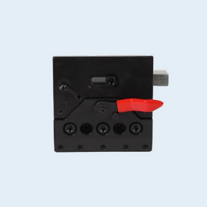
Press Brake Clamping
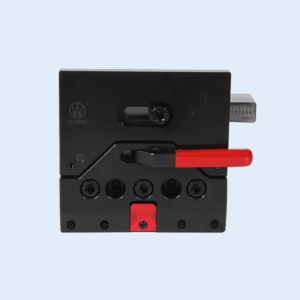
Press Brake Clamping
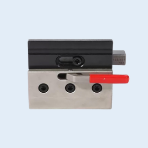
Press Brake Clamping
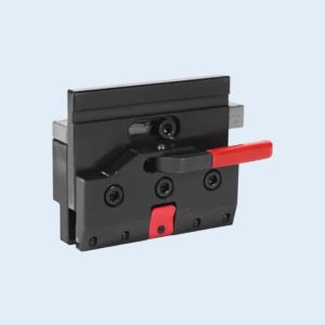
Press Brake Clamping
You check the angle finder and see 88 degrees on what should be a 90-degree bend, wondering how a half‑million‑dollar machine can miss a basic tolerance. The calculations look perfect, the backgauge hits its target within microns, yet the growing pile of rejected parts tells another story. In most cases, the blame falls on programming or backgauge calibration. But more often, the real culprit is clamp‑induced deflection—transforming a 100‑ton press into something that behaves like a 60‑ton machine. The backgauge positions the sheet exactly, but the beam flexes unevenly because the tooling isn’t securely locked down. Learn how secure Press Brake Clamping and matching Press Brake Toolings can restore your machine’s original precision.
Shops obsessed with mathematical perfection often scrap up to 20% more parts than those relying on laser‑verified setups, simply because they overlook the mechanical realities of tooling interfaces. Even on a press brake with ram repeatability tighter than ±0.001″, a mere 0.1 mm variance in stainless steel thickness can create an angular deviation of ±0.8–1.0°. This occurs when clamps fail to secure the tooling completely against the beam, producing a so‑called “phantom” tolerance stack-up.
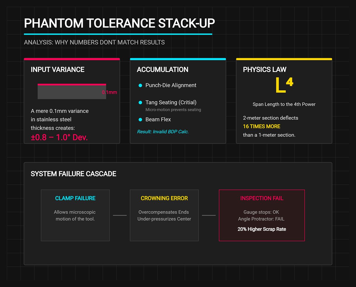
This misalignment accumulates across three key areas: punch‑die alignment, tang seating, and beam flex. If the clamp allows even microscopic motion, the tang won’t seat fully against the beam. When the press applies force, the tool shifts vertically before the metal actually starts to bend—instantly invalidating your bottom‑dead‑point calculations. You can minimize such variations by using properly fitted Amada Press Brake Tooling or Trumpf Press Brake Tooling, both engineered for consistency.
Machine physics magnifies the effect. Deflection risk increases with the fourth power of the span length (L⁴), meaning a 2‑meter section deflects sixteen times more than a 1‑meter one. If clamps permit micro‑movement, the programmed Press Brake Crowning system will overcompensate at the bed ends while under‑pressurizing the center. The result? A part that seems correct at the gauge stops but fails inspection on the angle protractor.
Finding the real cause means distinguishing hydraulic behavior from mechanical failure. Defective parts may look identical regardless of the source, but each issue demands a completely different solution.
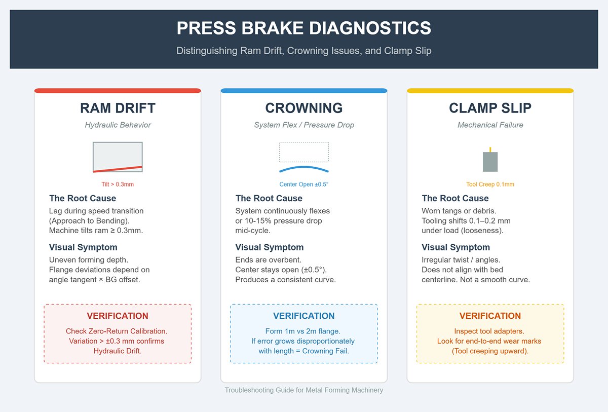
Ram Drift stems from hydraulic behavior, typically caused by lag during the speed transition. When the machine tilts the ram by 0.3 mm or more as it shifts from approach to bending speed, you’ll see flange deviations determined by the tangent of the angle multiplied by the backgauge offset. The result is uneven forming depth. To confirm, inspect the zero-return calibration: if variation exceeds ±0.3 mm, you’re dealing with hydraulic drift, not clamp issues.
Crowning Issues show a clear pattern: the ends of the part come out overbent while the center stays open by about ±0.5°. This happens when the hydraulic crowning system continuously flexes or when pressure drops 10–15% mid-cycle. A quick verification method is to form a 1‑meter flange and then a 2‑meter flange using identical settings. If angular discrepancies grow disproportionately with length, the crowning compensation is failing to counter the beam’s inherent deflection.
Clamp Slip is the trickiest to identify because it imitates crowning failure. In this case, the tooling shifts microscopically under load due to worn tangs or debris introducing 0.1–0.2 mm of looseness. Unlike crowning, which produces a consistent bend curve, clamp slip results in a twist or irregular angles that don’t align with the bed’s centerline. Examine your tool adapters closely: even wear marks running end‑to‑end indicate the tool is creeping upward into the beam during the bend, instead of the beam pressing the tool into the workpiece. In this situation, consider replacing your clamp components or upgrading with precision systems from JEELIX.
When a batch of high‑strength steel components fails quality inspection, the immediate assumption is often operator inconsistency. Yet the real culprit frequently lies in neglected material physics—specifically, stress relaxation. To reduce springback by 15–20% in high‑tensile metals, the ram must dwell at bottom dead center for 0.2–1.5 seconds. This brief pause enables “lattice slip,” allowing the material’s grain structure to stabilize.
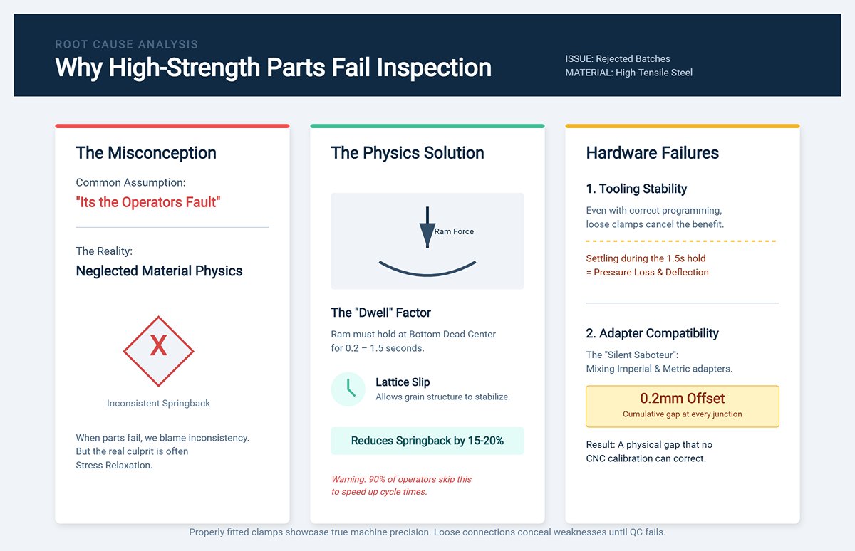
Roughly 90% of operators skip that dwell to speed up cycle times. Even when programmed correctly, it becomes ineffective if the clamps aren’t rock solid. Any movement or settling of the tooling during the 1.5‑second hold alters pressure and cancels out the intended springback reduction. The resulting deflection erases the potential benefit, turning what should have been a good batch into a pile of rejections. Reviewing clamp consistency via Standard Press Brake Tooling can help sustain uniform pressure throughout the stroke.
In addition, check all adapter interfaces for compatibility. Combining imperial and metric adapters can quietly sabotage hybrid tooling runs, introducing a cumulative 0.2 mm offset at every junction. That microscopic stack-up forms a physical gap that no amount of CNC calibration can correct. Properly fitted, uniform clamps showcase the press brake’s actual tonnage and precision capabilities; mismatched or loose connections conceal those weaknesses—until the quality control report turns red.
When a bend angle starts drifting mid‑run, most operators instinctively blame the material. They suspect a shift in grain direction or inconsistency in tensile strength between coils. If not the stock, they turn to the control system—adjusting Y‑axis depth or fine‑tuning the crowning settings in the program.
That reaction often sends them down the wrong path. While material variation is possible, it seldom explains the localized, unpredictable deviations that ruin precision bends. In most cases, the real issue is mechanical, hidden at the interface between the ram and tooling. Before sinking an hour into program edits that chase a physical fault, confirm that your clamping setup is mechanically sound. Improved seating with Press Brake Die Holder enhances this verification process.
You don’t need to dismantle the press to verify this. A quick, effective clamping diagnostic can be completed in less than a minute using simple tactile checks and basic shop supplies. If the press can’t hold the tooling completely rigid under forming load, no CNC compensation can prevent warped bends or inconsistent flange dimensions.
Although hydraulic and mechanical wedge systems are engineered to apply even pressure, real‑world wear rarely occurs evenly. The beam’s center—where most bending happens—tends to fatigue or gather debris more than its ends. The result is a set of “dead zones” where the clamp appears to engage but doesn’t actually hold the tooling securely.
For advanced clamping diagnostics, see the full Brochures with procedures from industry experts.
The fastest way to identify these areas is with a simple Paper Test. All you need is ordinary office printer paper, about 0.004 inches thick—no precision instruments required.
Procedure: Place narrow strips of paper between the tool tang and the clamp plate—or between the safety plate and the tool, depending on your configuration—at evenly spaced points along the bed, typically every 12 inches. Then engage the clamp.
Diagnosis: Move along the full length of the machine and try to pull each paper strip free.
If the paper holds tight at both ends of the ram but slips in the middle, the clamping force is uneven. This condition often mimics the effects of insufficient crowning, leading operators to over-adjust crowning when the real issue is that the tool is slightly lifting or tilting at the center of the machine.
A tool might pass the Paper Test yet still slip slightly during bending. This subtle movement, known as micro-slip, occurs because the static clamping force that holds the tool at rest differs from the dynamic holding power required during forming. When the ram descends and the punch meets the workpiece, the reaction force pushes the punch upward and, depending on its geometry, backward into the clamp.
If the clamping system has mechanical play—or if air trapped in the hydraulic circuit adds compressibility—the tool may shift as soon as bending force is applied. Studies show that air in hydraulic lines destabilizes the system under pressure, creating a “spongy” feel. In clamping terms, this means the grip seems firm at rest, but the hydraulic pressure can yield slightly when subjected to the 20 or 30 tons of forming load.
Detecting Micro-Slip: This movement is too small to see—it usually falls between 0.001 and 0.003 inches—but you can often hear it. A distinct “pop” or “click” when the punch contacts the sheet signals that the tool is reseating itself under load.
To verify this, position a dial indicator against the vertical face of the punch tang while the machine is clamped but inactive. Apply a moderate load (without actually bending material) or press gently on the tool by hand. If the indicator shows more than 0.001 inches of movement, the clamp is allowing slippage. Even this small amount of movement directly produces angular errors. For instance, if the punch rises by 0.004 inches, the Y-axis depth changes by the same amount, which can shift the bend angle by more than a degree—depending on the V-die opening.
The tool seat—the flat horizontal surface on the beam where the tool shoulders rest—serves as the foundation for your entire setup. Brands such as Amada and Trumpf manufacture their machines with ram position tolerances within about 0.004 inches along the entire length. However, localized wear on that tool seat can compromise this precision in certain areas of the bed.
Visual inspection alone won’t reveal the problem. Oil, grease, and uneven lighting can easily conceal significant depressions in the steel. You’ll need to rely on touch to find them.
The Fingernail Test: First, clean the seating surface thoroughly with solvent to remove oil and residue. Then, run your fingernail vertically along the clamp face and horizontally across the load-bearing shoulder. You’re feeling for a subtle “step” or ridge.
Most shops concentrate their work in the center of the press brake. Over years of use, that focused tonnage compresses and wears the center of the seat more than the ends. If your fingernail catches on a ridge as you move from the center toward either side, you’ve found evidence of seat wear.
If the tool sits even 0.002 inches lower in the center because of wear, you’ll constantly battle a “canoeing” effect, where the bend angle opens up in the middle. No level of clamping force can correct an uneven reference surface.
The tang on your tooling acts like a forensic record of how the clamp engages the tool. By studying the wear marks on the male tang of your punches, you can analyze and understand the clamp’s actual grip behavior.
Polished Horizontal Lines: If you notice distinct, polished lines running lengthwise along the tang, it’s a sign of vertical micro-slip. The clamp is applying enough pressure to create friction, but not enough to prevent the tool from sliding slightly up and down during bending. This pattern tells you the clamping pressure needs to be increased—typically by about 10–15% when working with smoother metals—or that the springs in a mechanical clamp may need replacement.
Spot Marks (Galling): Shiny circular impressions or deep gouges suggest point loading, meaning the clamping plate isn’t perfectly flat or has debris embedded in its surface. Instead of spreading the holding force evenly across the tang, the clamp bites down on a single spot. This lets the tool pivot or “rock” around that point, leading to angular variation as the punch tips forward or backward during bending.
Uneven Wear (Front vs. Back): When the tang shows heavy wear on the back side but looks nearly new on the front, it suggests the clamp is pushing the tool out of alignment rather than seating it squarely. This typically happens with worn mechanical wedge systems where the wedge drives the tool forward as it tightens instead of pulling it into correct position. The misalignment shifts the bend’s centerline, causing back-gauge readings to appear wrong—even when calibration is accurate.
Many fabricators think of press brake clamping in binary terms: the tool is either secure or it isn’t. As long as the punch doesn’t drop from the ram, they assume the clamp is functioning correctly. That’s a dangerously simplistic view. In truth, clamping is a dynamic variable that directly affects bending accuracy. A clamp isn’t merely a holder—it’s the main channel through which tonnage transfers. When that interface begins to degrade, you rarely get a catastrophic failure. Instead, you see subtle, inconsistent results—angles that vary, center-to-end differences, or unpredictable springback—problems often misattributed to the material or crowning system.
To troubleshoot bend accuracy properly, stop treating the clamp as a fixed component and start recognizing it as a mechanical system with its own performance degradation curve. Whether you’re applying torque manually or via automated hydraulics, the failure signatures follow consistent, predictable patterns—almost always unnoticed until inspection reveals the discrepancies.
The key failure point in manual clamping isn’t mechanical—it’s human. Because the system depends entirely on how consistently the operator applies force, the “human factor” becomes a measurable source of variation. Industry analyses indicate that gaps in operator technique account for nearly 30% of press brake tooling failures. However, this isn’t usually due to a lack of skill; it’s the inevitable outcome of inconsistent practice.
Take the torque placed on the wedge, for instance. A focused morning crew might achieve about ±0.5° repeatability using test bends. By contrast, a tired night shift crew often skips the “same mold height combination” rule to save time. In tracked production scenarios, that short-cut produced ±1.2° variation and increased reject rates by 15%. The clamp itself wasn’t at fault—the uneven torque distribution was. When a less experienced operator attaches a straight punch to a thick plate without ensuring the wedge is evenly seated, the resulting imbalance can distort bend angles by up to a full degree per part.
Another overlooked factor is wear. Manual wedge clamps are consumable components subject to fatigue. After roughly 80,000 bends without inspection or refurbishment, crack rates within the wedge mechanism rise by 40%. A worn wedge no longer ensures a perfectly vertical seat for the tool; instead, the tang may settle at a slight tilt. In response, operators often try to correct visible misalignment by overtightening certain sections—introducing even more variation into what should be a stable setup. The deterioration is subtle but significant: the clamp still holds the tool, just not accurately.
Hydraulic clamping delivers speed and high load capacity, but it comes with its own vulnerability—pressure decay and drift. Unlike manual clamps that stay fixed once tightened, hydraulic systems remain active. Any pressure drop directly reduces holding force, even though the tool may still appear firmly seated.
A pressure loss greater than ±1.5 MPa marks the danger zone. This decline accounts for about 15% of early punch failures because it allows the ram to subtly shift under stress. In practical terms, a 100-ton machine affected by hydraulic decay might deliver the effective resistance of just 60 tons when contact is made. The control system assumes the tool is locked solid, but in reality, the clamp permits micro-movements that compromise accuracy.
The underlying problem often stems from gradual seal deterioration—an issue that usually goes unnoticed. After around 500 hours of operation without proper oil maintenance, seals begin to break down, allowing air to infiltrate the hydraulic lines. Once air enters the system, it compresses under pressure, producing hydraulic “shocks” during the rapid transition from approach to bending. Operators report inconsistent bending angles and waste valuable time recalibrating the backgauge, unaware that the inconsistency originates in the clamp itself. The problem persists until scrap rates in the middle of production runs soar past 20%. The solution typically isn’t replacing hardware—it’s recalibration. In one documented case, a shop corrected an 80-millisecond servo delay caused by unstable hydraulic pressure simply by recalibrating its valves. This adjustment reduced angular variation across a 200-part run from 1.5° down to 0.3°.
Pneumatic systems are popular for their cleanliness and quick response, yet they tend to fail in a subtle and deceptive way. Because air is compressible, any leak doesn’t just reduce force—it compromises stability. Minor air leaks can produce issues similar to those in hydraulic systems, but here the telltale sign is vibration.
A small air leak can cut clamping force by 10–20%, leading to micro-slippage as the punch contacts the metal. This minute movement of the tool is often mistaken for bed deflection. The result is dimensional variation of about ±0.02mm per sensor discrepancy—too small to notice until the final piece shows a clear overbend.
Unlike hydraulic systems, which tend to fail abruptly, pneumatic failures develop gradually. A pinhole leak can cause a 2MPa pressure drop in as few as ten cycles, weakening the hold-down force and amplifying the natural vibrations of the press brake. These vibrations accelerate tool wear by up to 40% as the punch vibrates against the clamp. Field data underscores how serious this invisible fault can be: one plant recorded a 25% scrap rate while forming 3mm steel. Operators spent days adjusting crowning to no avail. The issue was finally resolved only after bleeding the air lines before each shift, which immediately restored angular consistency within ±0.5°.
The most damaging and difficult-to-detect source of error isn’t worn components or pressure decay—it’s geometric incompatibility. Combining American and European tooling systems creates a “compatibility trap” that undermines accuracy before the press brake even starts a cycle.
The root of the problem lies in the tang height. American tooling generally features a 1/2-inch tang, while European systems are designed around a 22 mm standard. This slight difference—just 0.5 to 1 mm—creates a subtle but critical misalignment when adapters are used interchangeably. Although the tool may physically lock into place, that disparity tilts it roughly 0.1 degrees off parallel. Over the entire beam length, those small deviations accumulate, producing angular errors of 1 to 2 degrees.
This phenomenon creates what’s known as a “phantom stack-up.” Everything appears correct to both the backgauge and the controller, yet under load, the offset shifts the tool’s point of contact within the V-die. As a result, the center of the bend can underperform—by as much as 40%—compared to the ends, since the tool isn’t evenly seated against the clamp’s load-bearing surfaces. Shops mixing these standards regularly report rework rates of around 30%. For instance, pairing imperial adapters with metric clamps often leads to a gradual loosening of about 0.02 mm per cycle. The digital program may be exact, but the physical interface keeps moving.
To confirm whether this issue is affecting you, conduct a quick visual check: examine the tang seat wear marks on your tooling. If grooves or abrasion appear only on one side, it’s a clear sign you’ve fallen into the compatibility trap.
| Section | Key Points | Failure Signature / Effect | Data / Statistics | Corrective Action |
|---|---|---|---|---|
| Every Clamping System Exhibits Its Own Distinct Failure Signatures | Clamping affects bending accuracy; degradation leads to subtle inconsistencies; operators often misdiagnose failures as material or crowning issues. | Variations in angles, center‑to‑end differences, unpredictable springback. | — | Treat the clamp as a dynamic system; monitor degradation and performance over time. |
| Manual Wedge Clamps | Human inconsistency causes variation; torque application differences between crews; wear increases misalignment; uneven torque creates angular deviation. | Inconsistent angles, tool tilt, over‑tightened sections, variable accuracy. | ±0.5° repeatability (morning crew) vs ±1.2° (night crew); 15% reject rate increase; 40% crack rate rise after 80,000 bends. | Standardize torque procedures; inspect and refurbish wedges regularly; avoid uneven seating. |
| Hydraulic Systems | Pressure decay reduces holding force; seal deterioration introduces air into system; unnoticed drift causes micro‑movements and angle errors. | Hydraulic “shocks,” ram shift, reduced tonnage efficiency, inconsistent bends. | ±1.5 MPa pressure loss threshold; 15% early punch failures; 100‑ton machine acts as 60‑ton with pressure loss; scrap >20%. | Maintain oil and seals; monitor pressure; recalibrate valves to correct servo delays (reduced variation 1.5°→0.3°). |
| Pneumatic Systems | Air compressibility causes instability; leaks reduce force and create vibration; gradual pressure drops lead to tool wear and variation. | Vibration, micro‑slippage, tool wear, dimensional variation (~±0.02 mm). | 10–20% loss of force from small leaks; 2 MPa drop in 10 cycles; 40% increase in tool wear; 25% scrap forming 3 mm steel. | Inspect and bleed air lines regularly; check for leaks; restore air pressure to stabilize angular accuracy (±0.5°). |
| The Compatibility Trap | Mixing American and European tooling creates tang height mismatch; results in off‑parallel seating and phantom stack‑up errors. | Angular errors (1–2°), uneven load transfer, bend center underperformance (up to 40%). | Tang height difference 0.5–1 mm (½‑inch vs 22 mm standards); ~30% rework rates; 0.02 mm loosening per cycle. | Use matching systems; visually inspect tang seat wear; avoid mixed imperial‑metric adapters. |
Even with top-tier hydraulics and precisely ground tooling, the link between the machine and the die remains at the mercy of one crucial element: the operator. The clamp functions as the handshake between the press brake’s force and the tool’s geometry. If that handshake is weak, misaligned, or obstructed, even the most advanced crowning and optical measurement systems won’t be able to correct the foundational mechanical error.
The following setup mistakes are not just poor practices—they’re mechanical saboteurs that alter the underlying physics of the bend. Understanding why these errors occur is the only way to prevent them from turning a precision process into a costly cycle of rework and wasted material.
The most frequent setup error starts with a quick glance rather than true alignment. An operator inserts multiple tooling sections, estimates the spacing by eye, and locks them in place. To the naked eye, the tool line may look perfectly straight—but under the immense forces of bending, “visually straight” quickly becomes mechanically disastrous.
When clamping pressure is applied to a tool segment that’s even slightly out of alignment, it creates uneven points of contact along the beam. Instead of spreading the load evenly across the full shoulder of the tool, the clamp generates concentrated stress points. As a result, the press brake behaves as though it has 20–40% less effective tonnage across the bend length. The hydraulics may deliver full power, but the force isn’t transmitted evenly through the interface.
Take, for example, a real-world case analyzed using tooling software such as the WILA Tool Advisor. A misalignment of just one degree over a 10-foot bed caused the peak loads to shift toward the machine’s ends, reducing the center tonnage by 28%. The resulting workpiece displayed the classic “canoe” defect: the ends were over-bent while the center remained under-bent.
Operators frequently mistake this for a crowning issue or variations in material properties. They spend valuable time adding shims or adjusting the crowning system, unaware that the real culprit lies in the clamping setup. That visually acceptable but mechanically flawed alignment creates a structural disadvantage that turns otherwise consistent CNC programs into batches of unusable parts.
In a fast-paced fabrication environment, setups are often changed in haste. An operator removes a tool, gives the working surface a quick wipe, and reinstalls a new one. The hidden problem lies on the seating surface—the tool tang and the inner face of the clamp—which often go unchecked.
Shop dust, metal fragments, and mill scale can measure as little as one-thousandth of an inch. When trapped between the clamp and the tool tang, these tiny particles don’t simply compress—they act like micro wedges. This interference can reduce the clamp’s holding strength by as much as 15%. Although the tool might appear firmly locked in place when idle, conditions change dramatically once the ram engages the sheet.
Under full pressure, that minuscule gap turns into a “slip zone.” The debris allows micro-movements that cause the upper beam to deflect unevenly. To the naked eye, the tool seems stable, but angle measurements reveal differences of two to three degrees. This happens because the ram’s full force isn’t transmitting straight through the tool—it’s being diverted by that thin debris wedge.
This introduces what operators often call a “phantom variable”—a setup that produced flawless parts at 8:00 AM starts drifting out of tolerance by 10:00 AM. The cause isn’t mystery; it’s the tool slowly settling through the layer of debris, changing the effective shut height. Every time a shift overlooks cleaning the seating surface, they’re effectively erasing the machine’s built-in ability to hold thousandths-of-an-inch precision.
A persistent myth lingers in many shops—that “tighter is better.” On the flip side, some operators favor a “gentle touch” in the belief that it preserves tool life. Both mindsets are counterproductive. They undermine repeatability, especially in manual clamping systems where tightening force depends on operator strength rather than a calibrated torque wrench.
The Autopsy of Over-tightening
When an operator exceeds the manufacturer’s torque specification by just 20%, the tool tang’s geometry changes. The excessive force distorts the metal, causing uneven pressure across the clamp. One side grips harder than the other, resulting in uneven wear. Over time, this distortion reduces repeatability by about half a degree per cycle. The tool no longer seats perfectly flat—it seats wherever the internal stress allows it to.
The Autopsy of Under-tightening
Under-tightening by as little as 10% triggers a different failure mode: float. Under full load—like the 19.7 tons per foot needed to bend 1/4-inch A36 steel over a 2-inch V-die—the tool must remain absolutely stable. If the clamp is not secure, the tool vibrates or shifts vertically during the stroke. This mimics ram drift and can sap 5–10% of available tonnage, diverting energy from metal forming into tool movement.
In manual setups, torque variation between operators can reach 30%. One person’s idea of “tight” might be another’s version of “loose.” The only reliable solution is to treat torque as a defined specification, not a matter of personal judgment. Without adherence to manufacturer guidelines, the clamp shifts from being a constant to becoming a variable that undermines consistency.
As shops grow and accumulate secondhand tools or machines from different brands, the tooling inventory often becomes a patchwork of standards. The most deceptive setup error occurs when metric and imperial tooling are combined on the same beam. To the eye, they appear interchangeable and fit the holder. In reality, their geometries differ enough to make precision-level results impossible.
European metric tools—commonly found on Amada and Trumpf systems—typically sit about 0.020 inches (0.5 mm) higher in the clamp than their American imperial counterparts, such as older Wila or Salas hybrids. When both types are used together in a single setup, the result is a staggered tang height across the beam.
This discrepancy creates a tonnage imbalance of roughly 15–25%. As the ram descends, the taller imperial tools contact the clamp and workpiece first, taking most of the load. Meanwhile, the shorter metric tools either remain slightly disengaged or come into contact later in the stroke. This leads to what’s known as a “phantom tolerance stack‑up.” Even if the backgauge is perfectly calibrated, bend angles can drift by 1–2 degrees along the part length because one side of the setup is overloaded while the other receives too little force.
Studies show that about 73% of setups using mixed‑standard tooling fail their first‑article inspections. The underlying issue is frequently misdiagnosed—operators often compensate by adjusting the crowning, assuming the bed has deflected, when the real problem is the physical height mismatch between tooling tangs. Mixing metric and imperial tools doesn’t save time; it guarantees inconsistency.
When bend angles start drifting and operators keep chasing the backgauge, the first instinct is often to blame the hydraulics or the material batch. But if the tool isn’t firmly seated against the beam, even the most precise machine can’t repeat accurately—you’re essentially bending on an unstable foundation.
You can’t afford to wait weeks for a service technician. You need good parts off the press before the next shift. The following interventions are prioritized from the fastest on‑the‑floor fix to long‑term investment—each designed to get you back to full production as quickly as possible. For ongoing optimization, explore compatible Panel Bending Tools and Punching & Ironworker Tools to round out your fabrication lineup.
If you notice angle variations along the part length, stop tweaking the crowning settings. The true cause is often microscopic debris.
In a press brake environment, mill scale and fine metal dust behave almost like fluid, creeping into the microscopic gap between the clamp and the tool tang. A single chip only 0.002 inches thick trapped between the tool shoulder and clamp face can introduce roughly one degree of bend angle error.
Action Step: Carry out the “Stuck Tool” procedure.
If your bend angle immediately stabilizes after this reset, the issue isn’t mechanical failure—it’s poor maintenance discipline.
If your tools are clean yet you still hear a “pop” or “creak” while bending, the clamping force is too low for the load you’re applying. On the other hand, if clamp bolts are snapping or tool tangs are deforming, you’re applying excessive torque.
Clamping isn’t simply an on/off condition—it’s a variable force. It must exceed both the stripping force during the return stroke and the horizontal deflection forces generated during bending.
For manual clamps: Stop using a cheater pipe on an Allen key. It produces uneven torque along the clamping beam, resulting in a bowed tool line.
For hydraulic clamps: Inspect your hydraulic line pressure—pump seals naturally degrade over time, leading to a drop in pressure.
Sometimes, no amount of adjustment will help because the clamp geometry itself has shifted. Wear rarely happens evenly—it tends to accumulate in the areas where most of the work is performed.
The “Canoe” Effect: In most shops, small parts are bent in the machine’s center. Over several years, this causes uneven wear—wedges or clamp plates in the middle degrade, while the ends remain nearly untouched. When you later mount a full-length tool, the ends grip firmly, but the worn center stays loose. The result: the tool arches upward in the middle, forming a distinctive “canoe” shape.
Diagnostic Procedure:
For Hydraulic Systems: Watch for the telltale “Weep.” In hydraulic clamping systems that rely on bladders or pistons, oil residue across the top of your tool tangs after removal signals a failed seal.
Eventually, the cost of maintaining manual clamps outweighs the expense of upgrading to a modern clamping system. This threshold is crossed when your setup time regularly consumes more hours than your production runs.
If you’re swapping tools four times each shift and every change takes 20 minutes, you’re losing about 80 minutes a day to wrench work. That adds up to nearly seven hours a week—effectively a full shift lost just to tightening and loosening bolts.
ROI Calculation: Take your shop rate (say, $100/hour) and multiply it by the total hours lost to setup each month (for example, 28 hours). Monthly Cost of Manual Clamping: $2,800.
A retrofit hydraulic or push-button quick-change setup typically costs between $15,000 and $25,000. At $2,800 in recovered billable time per month, the system pays for itself within six to nine months—and every month thereafter translates directly into profit. You can evaluate upgrade options through JEELIX or Contact us for a tailored system review.
Manual clamping also depends on human consistency and strength. By mid-afternoon, fatigue takes a toll. An automated system applies the same precise force at 2:00 PM as it did at 7:00 AM, ensuring uniform results throughout the shift.
This loops back to the central troubleshooting question: “Why can’t we hold the angle?”
In most cases, the issue isn’t operator skill—it’s the condition of the tools. Expecting precision from worn or inconsistent clamps is like expecting surgical accuracy with dull instruments. Once you eliminate clamping variability, you stop chasing the angle and start mastering it.
 العربية
 বাংলা
বাংলা
 Български
 Čeština
 Dansk
Dansk
 Nederlands
 Suomi
Suomi
 Français
 Deutsch
 Ελληνικά
 עִבְרִית
 हिन्दी
 Magyar
 Bahasa Indonesia
 Italiano
 日本語
日本語
 Қазақ тілі
 한국어
한국어
 Bahasa Melayu
 Norsk bokmål
 فارسی
فارسی
 Polski
 Português
 Română
 Русский
 Српски језик
 Slovenčina
 Español de México
 Español
 Kiswahili
 Svenska
 Tagalog
 தமிழ்
தமிழ்
 ไทย
ไทย
 Türkçe
 Українська
 اردو
اردو
 Tiếng Việt
 简体中文
简体中文
 香港中文
香港中文
 繁體中文
繁體中文
