Showing 1–9 of 13 results
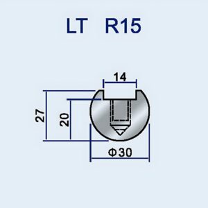
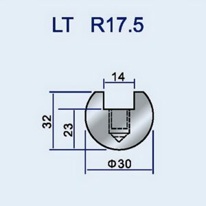
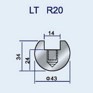
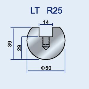
Radius Tools, Radius Press Brake Tooling
Radius Tools, Radius Press Brake Tooling
Radius Tools, Radius Press Brake Tooling
Radius Tools, Radius Press Brake Tooling
Radius Tools, Radius Press Brake Tooling
Radius Tools, Radius Press Brake Tooling
Radius Tools, Radius Press Brake Tooling
Radius Tools, Radius Press Brake Tooling
Radius Tools, Radius Press Brake Tooling
Last Tuesday, a junior engineer handed me a purchase order for $1,200 worth of carbide corner-rounding end mills. When I asked what they were for, he said Quality Control needed “radius tools” for a new batch of aerospace brackets. I walked him into the inspection room, pointed to the granite surface plate, and reminded him that QC doesn’t cut metal—they measure it. He was about to issue a weapon to someone whose job is simply to verify the scene.
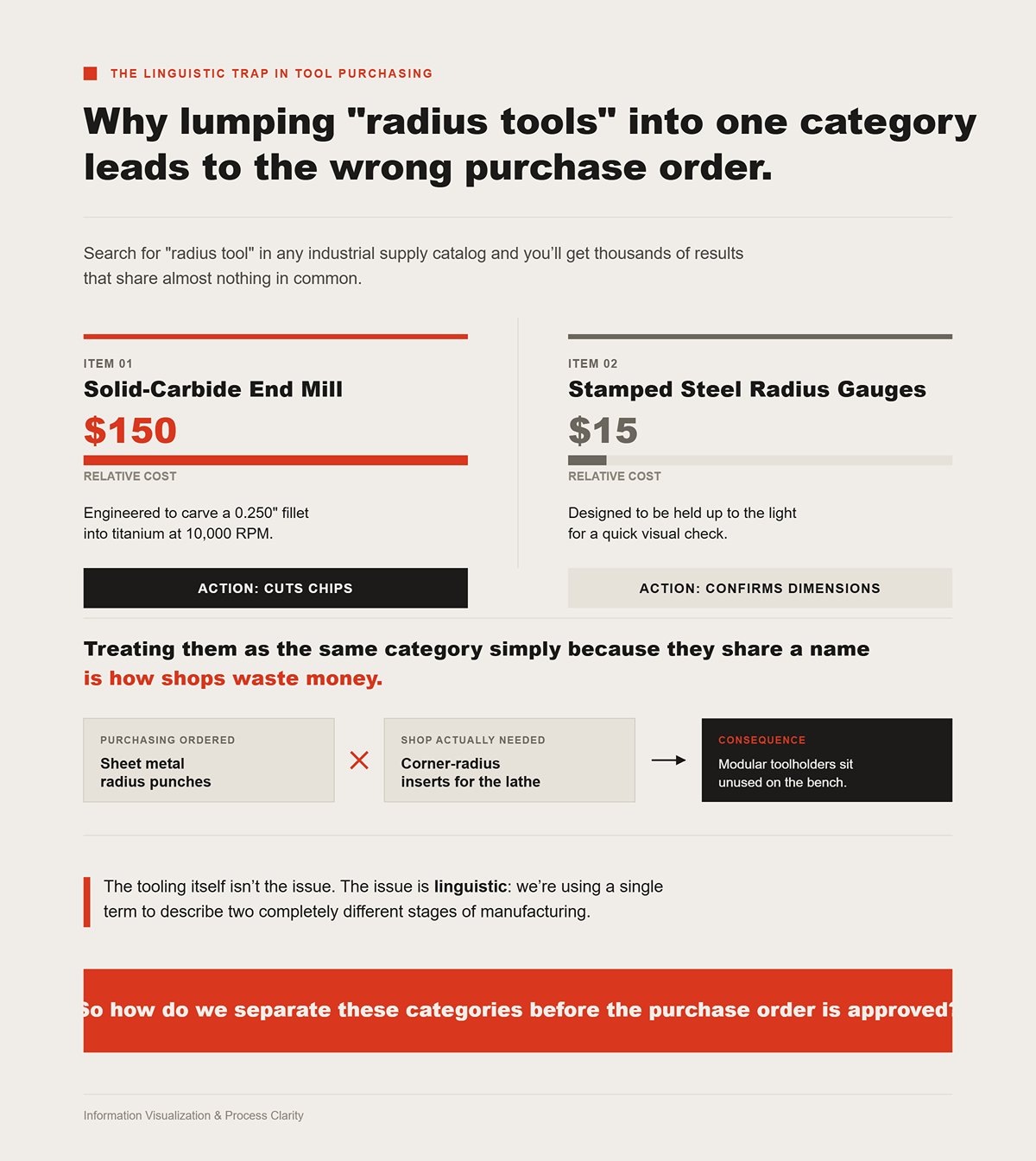
Search for “radius tool” in any industrial supply catalog and you’ll get thousands of results that share almost nothing in common. At the top of the list might be a $150 solid-carbide end mill engineered to carve a 0.250″ fillet into titanium at 10,000 RPM. Right beside it, you’ll find a $15 set of stamped steel radius gauges designed to be held up to the light for a quick visual check.
One cuts chips. The other confirms dimensions.
Treating them as the same category simply because they share a name is how shops waste money. Modular toolholders sit unused on the bench because Purchasing ordered sheet metal radius punches instead of corner-radius inserts for the lathe. The tooling itself isn’t the issue. The issue is linguistic: we’re using a single term to describe two completely different stages of manufacturing.
So how do we separate these categories before the purchase order is approved?

Think of the shop floor as a courtroom. There’s the executioner—and there’s the inspector.
The generative tool—the cutter, the punch, the insert—is the executioner. Its role is forceful and irreversible: it removes material. When an operator mounts a modular holder with a semicircular radius punch, they are physically imposing a curve onto raw stock.
The diagnostic tool—the gauge, the optical comparator, the CMM probe—is the inspector. Its role is validation. It removes nothing. It simply determines whether the executioner performed as required.
Confusing the two is like handing a micrometer to a contract killer.
Programmers make this mental leap all the time. They lean on cutter compensation in the CNC code to offset the tool nose radius, reducing a physical tool to a set of numbers. In doing so, they forget that on the shop floor, cutting heat, tool deflection, and the subjectivity of measurement don’t care about software offsets. The code may handle the math, but the metal still responds to physics. If the software solves the geometry, why do the wrong physical tools keep ending up in the wrong drawers? To avoid this, a clear understanding of your tooling inventory is key. For a comprehensive look at execution tools for forming operations, explore our range of Press Brake Toolings.
Walk into your tool crib and open a few drawers. Chances are, you’ll find subjective radius gauges stored in the same cabinet as high-performance corner-radius end mills. Suppliers structure their websites the same way, organizing products by geometric shape instead of manufacturing function. That subtle misclassification pushes operators into reactive workflows. An inspector struggles to verify a tiny radius with a leaf gauge and rejects the part. The engineer assumes the cutter was wrong and orders a different corner-rounding end mill—never realizing the generative tool was correct and the diagnostic tool was the weak link.
We’ve allowed catalog taxonomy to shape our machining strategy. To break that cycle, shift your perspective from tool geometry to machine intent. Are you about to clamp this piece of metal in a spindle to make chips, or are you setting it on a granite surface plate to measure it?
Last month, I pulled a $150 solid-carbide corner-rounding end mill from the scrap bin. It had snapped cleanly at the shank. The programmer had tried to hog a half-inch radius in 4140 steel in a single pass, treating the tool like a magic wand that could simply paint a perfect curve onto the edge of a part. But the spindle doesn’t perform magic. It delivers force.
When you clamp a generative tool into a collet, you’re commissioning an executioner to remove metal. If you don’t understand how that specific geometry engages the material—where the load concentrates, how the chip forms, how heat evacuates—you’re not machining. You’re gambling with carbide. So how do you match the executioner’s blade to the job?
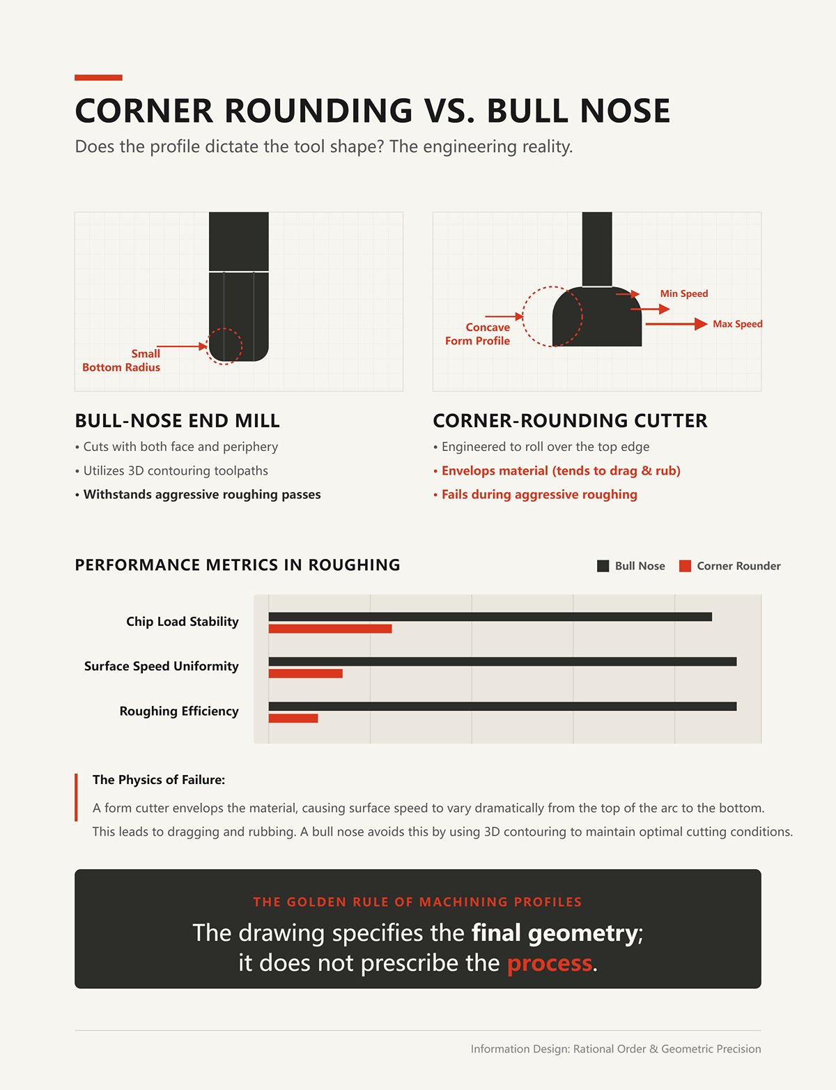
Place a bull-nose end mill next to a corner-rounding form cutter and the differences are obvious. A bull nose features a small radius ground into its bottom corners and cuts with both its face and its periphery. A corner rounder, by contrast, has a concave profile engineered to roll over the top edge of a part. A junior engineer sees a drawing that calls for a 0.250″ external fillet and instinctively grabs a 0.250″ corner rounder. That instinct is often wrong.
A form cutter envelops the material, which means the surface speed varies dramatically from the top of the arc to the bottom. It tends to drag and rub—and if you try to rough with it, it will fail. A bull nose, however, can machine the same profile using 3D contouring toolpaths, maintaining a consistent chip load and withstanding aggressive roughing passes. The drawing specifies the final geometry; it does not prescribe the process. If a bull nose can rough the feature safely and efficiently, why keep form cutters in inventory at all?
We stock them because function outweighs form. When I see a radius on a print, my first question isn’t about the dimension—it’s about purpose. What is this curve meant to accomplish?
If it’s an aerospace wing rib, that internal radius is a mission-critical stress-relief feature. A sharp 90-degree corner concentrates stress and becomes a crack initiation point. In that scenario, the radius must be flawless—smooth, consistent, and free of step-over marks. That typically requires a dedicated form tool or an exceptionally controlled finishing pass. There is no shortcut.
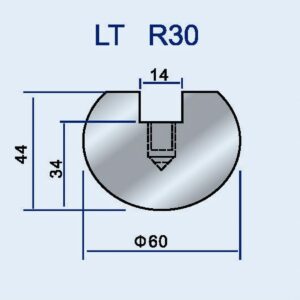
But if the same radius exists merely to break an edge so an assembler doesn’t cut a thumb, spending ten minutes of spindle time 3D-surfacing it with a ball mill is indefensible. You’re consuming machine time for a cosmetic detail. Before you choose the tool, you need to understand what the curve actually does. And when the radius truly is critical, how do you manage the physics of a tool wrapping around a corner? For applications requiring precise radius forming on sheet metal, specialized Radius Press Brake Tooling is engineered to handle these challenges with consistency.
When you drive a standard half-inch drill into a block of aluminum, the cutting forces are naturally balanced. But the moment you bury a corner-rounding form tool into an edge, the physics start working against you. You’re engaging a huge surface area all at once, and because the tool is curved, the cutting speed varies along the flute. Near the center, the tip is barely moving; at the outer diameter, it’s screaming. That imbalance sets up harmonic vibration—what we call chatter. It sounds like a banshee wailing inside the enclosure and leaves behind a washboard finish.
The typical reaction is to slow the feed rate to a crawl. That only makes things worse. The tool begins to rub instead of cut, the material work-hardens, and the cutting edge burns up. You can’t simply program a perfect arc and expect the metal to cooperate. You have to control the engagement angle, evacuate chips effectively, and maintain consistent tool pressure. When vibration spirals out of control, what’s the smartest way to bring the cutting edge back under command?
The instinctive move is to throw solid carbide at the problem. A solid carbide end mill is a single, rigid piece of material. It delivers maximum flute density and can maintain tight H9 tolerances on critical profiles. But rigidity isn’t the only path to edge control.
Indexable tools—steel bodies fitted with replaceable carbide inserts—shine when it comes to chip management. They generate thicker, more controlled chips at feed rates that would overwhelm a solid tool. Yes, an indexable cutter can chatter if you bury it full-depth into a contour. But if you’re roughing a large radius on a mold base, indexable is the clear choice.
Modern inserts, especially those with cermet cutting edges, are rewriting the old playbook. They’re delivering surface finishes that rival solid carbide while providing four usable cutting edges per insert. Crash a solid tool and you’ve just thrown $150 in the scrap bin. Crash an indexable, and you loosen a screw, rotate the insert, and get back to making chips.
The executioner has done its job. The material is gone. The curve now exists. But once the spindle stops and the dust settles, how do you prove the machine actually produced what the print specified? Ensuring your forming tools are held securely is just as critical; a reliable Press Brake Die Holder is fundamental for precision and repeatability.
| Aspect | Solid Carbide | Indexable Inserts |
|---|---|---|
| Structure | Single, rigid piece of carbide | Steel body fitted with replaceable carbide inserts |
| Rigidity | High rigidity | Less rigid than solid carbide in full-depth cuts |
| Flute Density | Maximum flute density | Limited by insert geometry |
| Tolerance Capability | Maintains tight H9 tolerances on critical profiles | Suitable for roughing and general profiling |
| Edge Control Approach | Relies on tool rigidity | Relies on chip control and insert geometry |
| Chip Management | Can struggle at very high feed rates | Excels at generating thicker, controlled chips at high feed rates |
| Performance in Deep Contours | More stable in full-depth contouring | Can chatter if buried full-depth into a contour |
| Best Use Case | Precision profiles and tight-tolerance work | Roughing large radii on mold bases |
| Insert Technology | Solid cutting edges only | Modern inserts (including cermet) rival solid carbide surface finish |
| Usable Cutting Edges | Single tool, no rotation | Typically four usable cutting edges per insert |
| Cost After Crash | Entire tool (~$150) may be scrapped | Rotate or replace insert; lower recovery cost |
| Post-Machining Verification | Requires measurement to confirm conformity to print specifications | Requires measurement to confirm conformity to print specifications |
“I walked him into the inspection room, pointed to the granite surface plate, and explained that QC doesn’t cut metal.” The spindle is the executioner—it removes material with force and finality. The gauge is the inspector. It is analytical, exacting, and entirely dependent on the geometry it contacts. Confusing the two is like handing a micrometer to a hired gun. A cutting tool cannot verify a dimension, and a gauge cannot bully a profile into tolerance. Once a part leaves the machine, the executioner’s role is finished. Operators don’t simply assume the print has been met. “They measure it.” But what, precisely, are they measuring? The physical metal itself—or the space surrounding it?
Last Tuesday, I scrapped a $500 aerospace bracket because a junior technician pressed a convex leaf gauge into a convex corner and decided the fit was “close enough.” He fundamentally misunderstood the tool’s purpose. When verifying a convex radius—an external corner—the gauge nests against the solid metal. But when checking a concave feature, such as an internal fillet, you’re evaluating negative space. You’re measuring air.
That distinction creates a serious procedural hazard. On a concave feature, a fillet gauge is effectively checking two independent criteria: leg length and throat thickness. A profile can pass leg length checks from both sides yet still fail throat thickness because the curve has flattened at the center. The gauge forces the inspector to measure the same feature in two different ways, introducing a vulnerability that even thorough training cannot completely eliminate. If the inspector verifies only one dimension, half the specification goes unchecked—and a structurally compromised part gets approved. If using the physical tool requires this level of interpretation, how much confidence should we place in the human eye reading the result?
The industry standard for these manual checks is the “light gap” test: press the gauge against the part, hold both up to the fluorescent lights, and look for any sliver of light bleeding through. It sounds foolproof—until you examine the mechanics. Accurate visual inspection with fillet gauges requires the tool to sit flush on the parent material at a perfect 90-degree angle. If the operator’s hand tilts even two degrees off-axis, the gauge can bridge the corner artificially, blocking the light and creating a false positive.
In other words, we are entrusting thousandths-of-an-inch tolerances to the steadiness of a human wrist.
It gets worse. These basic gauges assume ideal, perfectly perpendicular geometry. If the joint is skewed or the legs are unequal, the gauge’s logic collapses. Now you are forced into manual calculations just to interpret the actual profile. You are no longer simply checking for light—you are doing shop-floor trigonometry to determine whether the curve meets spec. And when the part itself violates the gauge’s built-in assumptions, “How do we split this category before the purchase order gets signed”? For complex or high-mix production, investing in the right tooling from the start is crucial. Discover precision solutions for major brands like Amada Press Brake Tooling or Trumpf Press Brake Tooling to ensure your forming processes are as accurate as your inspection demands.
The standard fixed leaf set—the Swiss Army knife of thin steel blades found in every machinist’s toolbox—demands a seven-step process. Select the leaf. Check the print. Confirm the angle. Calculate the offset. Measure the legs. Make the pass/fail call. Record the result. It is methodical—and painfully slow.
Modern laser inspection systems and adjustable optical scanners can evaluate skewed fillets in a single pass, with no manual math required. They eliminate the hunt for the correct leaf and remove the dependency on perfectly 90-degree seating. Yet shops still buy fixed leaf sets by the dozen.
Why? Because a $30 stamped-steel tool requires no calibration schedule, no batteries, and no software updates. It survives a fall onto concrete without complaint. Automated scanners cost thousands and demand software integration that can bog down a high-mix, fast-moving job shop.
So we make a trade: the absolute precision of a laser for the rugged immediacy of steel—accepting the human error that comes with it.
But when the manual inspector says the part is scrap and the CNC operator insists the machine cut it flawlessly, whose tool is actually telling the truth?
A brand-new $120 corner-rounding end mill plunges into a block of 6061 aluminum to machine a 0.250-inch external radius. The CNC operator runs the program. The spindle winds down. He pulls out an $80 radius leaf gauge and checks the corner. A thin line of light shows through the middle of the curve.
The CAM software insists the toolpath is mathematically perfect. The setup sheet confirms the correct tool is loaded. Yet the gauge declares the part scrap. So who’s wrong?
No one. The space between a perfect digital toolpath and physical reality is where profit margins disappear. “I walked him into the inspection room, pointed to the granite surface plate, and explained that QC doesn’t cut metal.” The gauge doesn’t care about your G-code, spindle speed, or the programmer’s intent. It responds only to what physically exists.
The cutting tool creates the geometry; the gauge verifies the result. If you don’t understand how those two instruments communicate, you’ll end up chasing phantom problems until the raw material runs out.
First-article inspection is more than a bureaucratic checkbox to satisfy aerospace auditors—it’s the proving ground for your tool offsets. Imagine the print specifies a 0.125-inch internal fillet. You load a 0.250-inch ball end mill and run the cycle. “They measure it.” The gauge rocks slightly in the corner, signaling the radius is undersized.
An inexperienced programmer’s first instinct is to run back and rework the CAM program. That’s a misunderstanding of the feedback loop. The print defines the required geometry; the gauge defines the necessary offset.
If the gauge shows the radius is off by three thousandths of an inch, you don’t rewrite the toolpath. You adjust the tool wear offset in the controller by 0.003 inches. The gauge is acting as a diagnostic device, revealing how much the cutter deflected under load or how spindle runout influenced the cut.
The cutter itself has no judgment—it goes exactly where it’s commanded. The gauge supplies the intelligence, telling you how to command it differently.
Carbide wears down. Machining is an aggressive, abrasive operation. A corner-rounding end mill may begin its life producing a flawless 0.500-inch radius, but after 50 passes through 4140 steel, that sharp cutting edge starts to erode. The setup sheet still lists the tool as a perfect 0.500-inch radius. The print calls for a 0.500-inch radius with a tolerance of ±0.005 inches. On part 51, the gauge no longer seats flush. The operator insists nothing has changed—the setup is the same, the code is the same, and the tool is still cutting. The print says otherwise. Who wins? The print always wins—and the gauge enforces that verdict.
This is precisely why lumping “radius tools” into a single budget category is so dangerous. You cannot recondition a radius gauge, and you cannot prevent an end mill from wearing out. Once the cutter’s physical geometry drifts from its programmed definition, the gauge is the only barrier between you and a rejected lot. “How do we divide this category before the purchase order is signed?” You purchase cutting tools with the expectation that they will wear out. You purchase gauges with the expectation that they will tell you exactly when that moment arrives. For reliable, long-lasting execution tools, consider industry-standard options like Standard Press Brake Tooling or explore solutions for European machine styles with Euro Press Brake Tooling.
When operators fail to understand this feedback loop, the financial damage is immediate and substantial. Just last month, I watched a second-shift operator chase a poor gauge fit by repeatedly lowering the Z-axis offset on a chamfer mill. He saw a gap on the gauge and assumed the tool was not cutting deep enough. What he missed was that the cutter had chipped.
He scrapped four titanium aerospace flanges at $800 each before anyone intervened. That is $3,200 in raw material and six hours of spindle time erased—simply because he mistook a geometric defect in the cutter for a positional error in the machine.
Ambiguity costs you $200 an hour in machine time while operators stand over the control panel debating whether to trust the cutter, the gauge, or the print. If you do not enforce a strict hierarchy on the shop floor—where the gauge diagnoses, the operator interprets, and the offset compensates—you are not operating a manufacturing facility. You are operating a casino.
Are we really still claiming that a stamped strip of sheet metal can validate a true profile? Once your tolerances tighten below two thousandths of an inch, relying on a hard gauge becomes a reliable way to stockpile scrap—parts that technically “passed.” We’ve already established the hierarchy: the cutting tool executes; the gauge inspects. A standard radius leaf gauge is a blunt instrument, dependent on the human eye spotting light through a sliver of a gap. When that gap is half the thickness of a human hair, your eye stops being a measuring device and starts being a guessing machine.
At what point does contact inspection shift from safeguard to liability? The limit isn’t merely dimensional—it’s physical. If you’re machining a standard 304 stainless bracket to ±0.005 inches, an $80 radius gauge set is perfectly adequate. But tighten that tolerance to 0.0005 inches on a micro-machined calcium fluoride lens, and physics begins to work against you. A hard gauge requires physical contact. On a high-polish surface, pressing a hardened steel template against the profile to verify curvature can scratch a component that already consumed $1,200 in spindle time.
“They measure it.”
Yes—they measure it with a tool that damages the product. The executioner performed flawlessly, but the inspector contaminated the evidence. You cross the micro-tolerance threshold the moment manual verification introduces more error—or more risk—than the machining process itself.
When a simple 2D corner radius evolves into a complex 3D blended surface, a flat stamped gauge can no longer physically nest into the geometry. This is typically when junior engineers start advocating for a $150,000 investment in a 3D optical profilometer. Optical systems can map a surface in under 30 seconds, resolving topography down to the nanometer—without ever touching the part. On paper, it sounds like the ultimate inspection solution.
“How do we draw the line in this category before the purchase order is signed?”
You separate the categories by understanding the limitations of light itself. Single-shot optical profiling is fast, but it depends on surface contrast to function properly. When you’re inspecting a perfectly uniform, mirror-polished radius, the camera struggles to reconstruct accurate topography. Low-contrast features generate digital artifacts. Suddenly, your $150,000 optical system is flagging defects that don’t exist, forcing operators to revert to the very hard gauges you were trying to eliminate. You don’t purchase an optical system because it feels like the future. You purchase it because the geometry of your 3D blend makes physical contact measurement impossible.
“I walked him out to the inspection room, pointed to the granite surface plate, and reminded him that Quality Control doesn’t cut metal.”
This is the final rule of thumb for your shop floor. Treating “radius tools” as a single line item in the budget is a semantic trap that quietly drains your tooling dollars. The next time an engineer submits a purchase request for a “radius tool,” ask one direct question: Are we trying to cut a curve into the part, or are we trying to verify that it meets the print?
If they’re cutting, you’re buying an execution tool. You evaluate carbide grades, flute geometry, and tool life. You fully expect it to wear out.
If they’re verifying, you’re buying an inspection instrument. You evaluate resolution, risk of surface damage, and calibration intervals. You expect it to deliver objective truth.
Confusing these two categories is like handing a micrometer to a hitman. Stop purchasing tooling based on the geometry it touches. Start investing in equipment based on the precise job you’re hiring it to do. For specialized forming needs beyond standard radii—such as complex profiles, panel bending, or laser cutting support—explore solutions like Special Press Brake Tooling, Panel Bending Tools, or Laser Accessories. To discuss your specific application and get expert recommendations, don’t hesitate to Contact us. You can also download our detailed Brochures for comprehensive product information.
 العربية
 বাংলা
বাংলা
 Български
 Čeština
 Dansk
Dansk
 Nederlands
 Suomi
Suomi
 Français
 Deutsch
 Ελληνικά
 עִבְרִית
 हिन्दी
 Magyar
 Bahasa Indonesia
 Italiano
 日本語
日本語
 Қазақ тілі
 한국어
한국어
 Bahasa Melayu
 Norsk bokmål
 فارسی
فارسی
 Polski
 Português
 Română
 Русский
 Српски језик
 Slovenčina
 Español de México
 Español
 Kiswahili
 Svenska
 Tagalog
 தமிழ்
தமிழ்
 ไทย
ไทย
 Türkçe
 Українська
 اردو
اردو
 Tiếng Việt
 简体中文
简体中文
 香港中文
香港中文
 繁體中文
繁體中文
