Showing 1–9 of 31 results
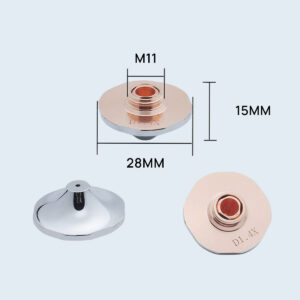
Laser Nozzle, Laser Accessories
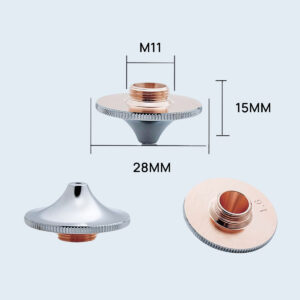
Laser Nozzle, Laser Accessories
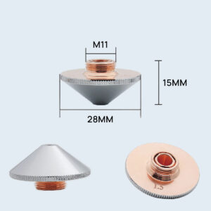
Laser Nozzle, Laser Accessories
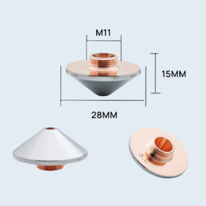
Laser Nozzle, Laser Accessories
Laser Nozzle, Laser Accessories
Laser Nozzle, Laser Accessories
Laser Nozzle, Laser Accessories
Laser Nozzle, Laser Accessories
Laser Nozzle, Laser Accessories
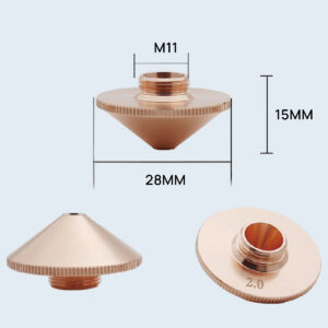
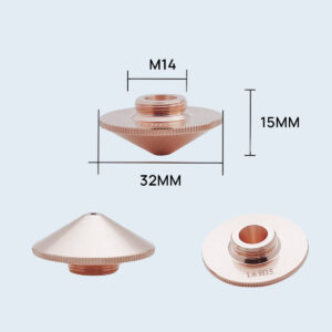
You are staring at a jagged, dross-caked edge on a sheet of quarter-inch stainless, your finger hovering over the console to crank the laser up another kilowatt. Stop. Step away from the dial. You think the beam is struggling to punch through, so you want to hit it with a bigger hammer. But look at the tip of the cutting head. That generic $15 copper nozzle you grabbed from the spare parts bin threaded on just fine, didn’t it? It looks like a simple metal funnel. It is not. You are trying to fire a sniper bullet through a sawed-off shotgun barrel, and adding more gunpowder is only going to blow the action right into your face.
The M11 threads on that discount bin nozzle bite perfectly into the ceramic ring. It seats flush. To the naked eye, it looks exactly like the OEM part we just trashed. Because it physically fits, you assume it mechanically functions.
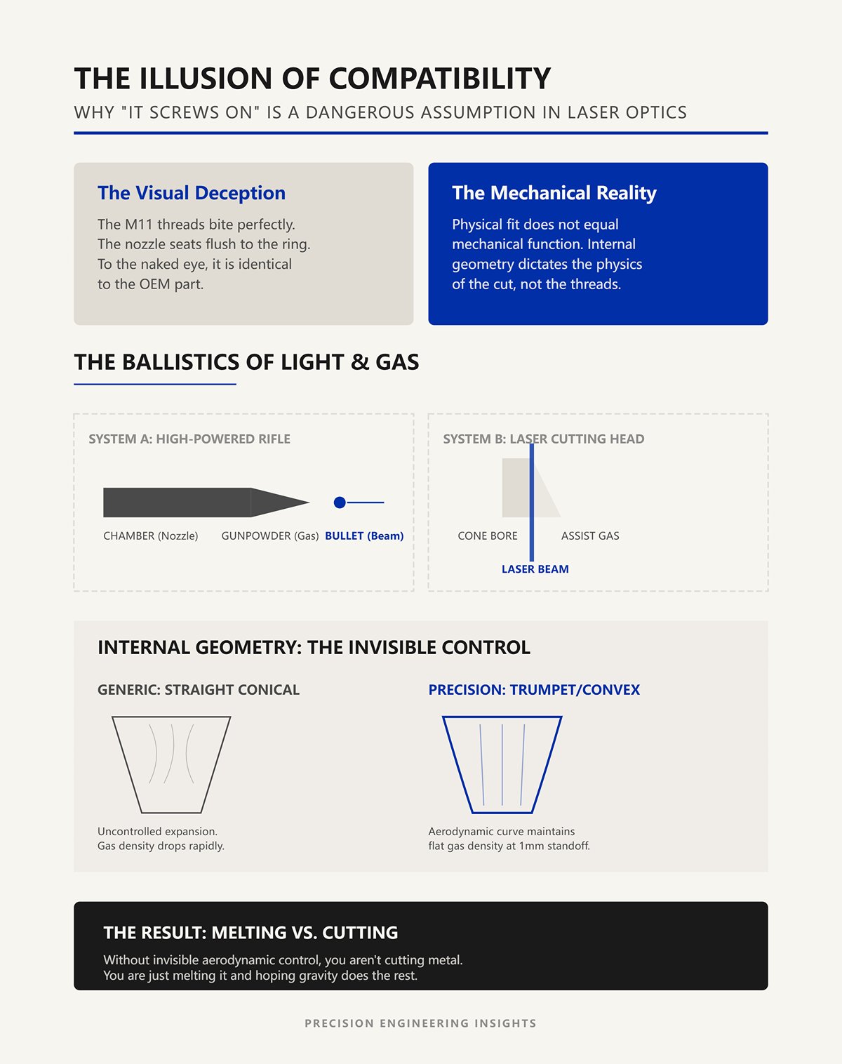
Let’s reframe what is actually happening inside that brass cone. A laser nozzle is not a garden hose sprayer. It is the chamber of a high-powered rifle. Think of the assist gas as your gunpowder, and the laser beam as your bullet. If you mismatch the chamber to the caliber, the bullet might still exit the barrel, but the expanding gases will violently backfire. A generic nozzle might have a straight conical bore, but your specific cutting parameters might require a trumpet-shaped convex curve to keep the gas density flat at a one-millimeter standoff. You lose that invisible aerodynamic control, and suddenly you aren’t cutting metal. You are just melting it and hoping gravity does the rest. This level of precision engineering is akin to what you’d expect from high-performance Press Brake Toolings, where geometry is everything.
Watch what happens when nitrogen hits 15 bar through a poorly machined converging nozzle. Right at 0.46 times the diameter distance from the exit—exactly where the gas is supposed to hit the cut front—the centerline momentum plummets. Normal shock diamonds form in the jet stream. The gas literally chokes on its own turbulence.
When the assist gas stalls, it fails to evacuate the molten kerf. The liquid metal pools. Your apprentice instinct is to crank the wattage from 4kW to 6kW to force the cut.
If [Molten metal pools in the kerf], Then [Do not increase power; check the gas flow profile].
Adding power to a stalled cut just creates a larger pool of boiling steel. The beam is doing its job perfectly. The issue is that your “gunpowder” is detonating outside the chamber instead of driving the molten material down through the bottom of the plate.
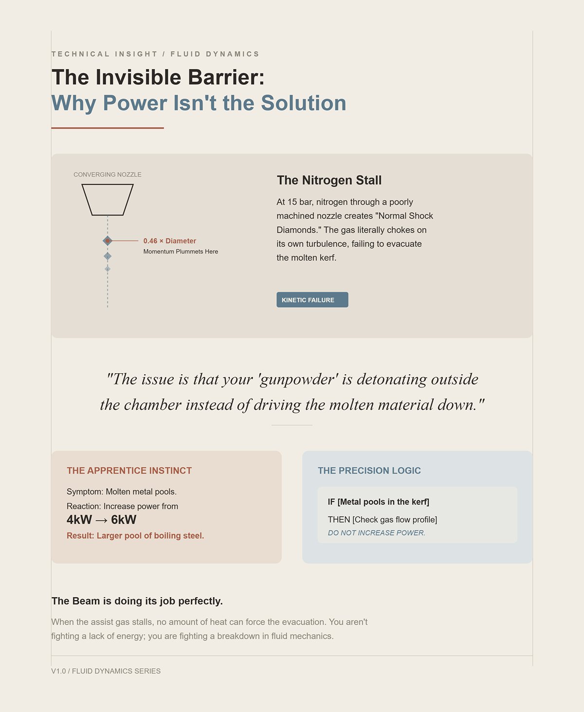
That boiling pool of steel doesn’t just sit there. It turns into a highly reflective, chaotic mirror.
When a 6kW fiber laser hits a convex pool of liquid metal that the gas failed to clear, the beam bounces straight back up the nozzle orifice. If [Gas dynamics fail to clear the kerf], Then [Back-reflection will travel up the beam path]. That generic $15 nozzle you saved money on just redirected raw, unfocused laser energy directly into the cutting head. It hits the protective window first, superheating any surface contamination, and then it finds the $4,500 focusing lens. The lens doesn’t just crack. It shatters, baking a toxic slurry of fused silica dust into the internal housing of a $150,000 cutting head.
Scrap Test: Pull your protective window and hold it under a bright inspection light at a shallow angle. If you see a constellation of microscopic white pits on the downward-facing side, your nozzle isn’t controlling the gas dynamics. You are already experiencing micro-back-reflections, and your expensive lens is living on borrowed time.
Pull a sheet of quarter-inch mild steel off the pallet and set it up for an oxygen cut. Oxygen is not just a shield; it is an active participant. It creates an exothermic reaction, literally burning the iron to generate additional heat ahead of the laser beam. You do not need the gas to act as a blunt-force battering ram. You need it to feed a highly localized fire.
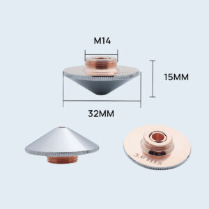
A single-layer nozzle tapers down internally like a simple, smooth cone. As the oxygen travels down this convergent funnel, it accelerates into a tight, needle-like stream. The geometry forces the gas to pinch exactly at the beam’s focal point. This single, focused jet drives the exothermic burn straight down the kerf without over-feeding the surrounding metal. The single-layer shape wins here because its simplicity guarantees a high-velocity, narrow column of gas that clears the thin liquid slag before it can solidify.
But what happens when the material changes, and the gas no longer fuels a fire, but has to physically punch a viscous slug of molten chromium out of the kerf?
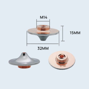
Switch that mild steel for a sheet of 304 stainless. You swap the oxygen for nitrogen. Nitrogen is inert. It does not burn. It just pushes. You will hear a lot of chatter from tooling reps about the strict “double-layer requirement” for stainless. The theory sounds bulletproof: a double-layer nozzle uses an inner core to blast the melt, while an outer tier creates a secondary gas curtain to shield the hot edge from atmospheric oxygen.
So you thread on a double-layer nozzle, crank the nitrogen to 20 Bar, and hit start.
The result is a bottom edge caked in sharp, jagged burrs and stained a sickly, oxidized yellow. The theory failed. Why? Because a standard double-layer nozzle is geometrically designed to expand and slow down the gas to create that protective outer curtain. If [Cutting stainless with high-pressure nitrogen], Then [Do not use a standard double-layer nozzle; the internal expansion chamber will choke your velocity]. Nitrogen requires sheer mechanical force to evacuate stainless slag. When you force 20 Bar of nitrogen through a double-layer nozzle, the dual-port design drops the exit velocity. The gas loses its shearing power. The molten metal clings to the bottom edge, superheats, and oxidizes in the turbulent wake. To get that clean, silver edge on stainless, you actually need the unrestricted, high-velocity punch of a single-layer nozzle—or a highly specialized, adjustable dual-port nozzle specifically machined for high-pressure jets. The need for specialized tooling for specific materials and processes is a principle well understood in metal fabrication, whether it’s for laser nozzles or for Standard Press Brake Tooling.
If high velocity is the absolute secret to shearing stubborn slag, why can’t we just blast every thick material with maximum pressure through a single-layer cone?
Load a sheet of one-inch thick carbon steel onto the slats. You switch back to oxygen. Remembering the clean cut on the quarter-inch plate, you keep the single-layer nozzle but step up to a massive φ3.0mm orifice, assuming more gas equals more cutting power. You fire the laser. Instantly, the cut front erupts. Sparks violently eject upward, and the kerf fills with boiling, uncontrolled dross.
Supersonic flow becomes a liability when the material relies on a slow, stable chemical reaction deep inside a thick kerf.
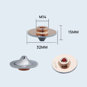
When high-speed oxygen from a single-layer nozzle hits a deep reaction pool, the sheer kinetic energy of the gas blows the molten iron apart. The gas flow separates from the vertical cut walls, creating chaotic, low-pressure vortexes inside the kerf. The exothermic reaction spirals out of control, causing rough, heavily gouged edges. This is exactly where the double-layer nozzle becomes mandatory. Operating at a surprisingly low 0.5 to 5 Bar, the double-layer design creates a stable, low-velocity gas curtain. It gently feeds the burn all the way down a one-inch kerf without detonating the pool and blowing a geyser of liquid steel right back up into your $800 protective window.
Scrap Test: Run your bare thumb along the bottom edge of your test cut. If you feel a solid ridge of turbulent, jagged slag that requires a grinder to remove, your internal nozzle aerodynamics are fighting your gas pressure. You are either choking a nitrogen shear with a double-layer nozzle, or you are blowing an oxygen reaction apart with a single-layer jet.
| Scenario | Material | Assist Gas | Nozzle Type | Aerodynamic Behavior | Resulting Edge Quality |
|---|---|---|---|---|---|
| Thin material oxygen cutting | Quarter-inch mild steel | Oxygen | Single-layer (convergent) | Gas accelerates into a narrow, high-velocity jet that pinches at the focal point and feeds a localized exothermic reaction | Clean kerf, minimal slag, sharp edge |
| Incorrect setup for stainless | 304 stainless steel | Nitrogen (20 Bar) | Standard double-layer | Internal expansion slows gas velocity; outer curtain design reduces shearing force | Jagged burrs, heavy bottom slag, yellow oxidation |
| Correct approach for stainless | 304 stainless steel | Nitrogen (high pressure) | Single-layer or specialized high-velocity dual-port | Unrestricted, high-velocity jet mechanically shears molten slag from kerf | Clean, silver edge with minimal burr |
| Overdriven oxygen cutting | One-inch carbon steel | Oxygen | Single-layer with large orifice | Supersonic gas disrupts reaction pool, creates turbulence and vortexes in deep kerf | Rough, gouged edges, uncontrolled dross, upward spark ejection |
| Thick material oxygen cutting | One-inch carbon steel | Oxygen (0.5–5 Bar) | Double-layer | Low-velocity, stable gas curtain gently sustains exothermic reaction through deep kerf | Stable cut, controlled slag flow, protected optics |
| Diagnostic scrap test | Any material | Any | Any | Edge condition reveals mismatch between gas pressure and nozzle aerodynamics | Smooth edge = correct setup; jagged ridge = nozzle and gas fighting each other |
The nozzle isn’t a cheap garden hose sprayer; it’s the chamber of a high-powered rifle. The assist gas is the gunpowder, the beam is the bullet, and if you mismatch the chamber to the caliber, the backfire will blow the optics right out of the cutting head.
Look at the flow meter on your bulk nitrogen tank. A 2.0mm nozzle running at 10 liters per minute creates a stiff, functional column of gas. Suppose you lose that nozzle and grab a 4.0mm replacement from the drawer, assuming the beam will clear it just fine. You do not just double your gas consumption. Because flow rate scales to the square of the orifice diameter, that 4.0mm opening requires 40 liters per minute just to maintain the exact same kerf pressure. You are instantly bleeding four times the volume of gas.
You are hemorrhaging $60 of nitrogen an hour just to get a jagged edge that looks like it was chewed by a rat.
Operators think a bigger hole guarantees the beam won’t clip the copper. But the nozzle is an aerodynamic choke point. When you oversize the aperture, the gas expands outward instead of driving downward. The pressure drops off a cliff before it even hits the surface of the sheet. If [Cutting 16-gauge sheet metal with nitrogen], Then [Do not exceed a 1.5mm nozzle diameter]. Anything larger diffuses the kinetic energy required to shear the molten slag. The gas spreads across the top of the plate, the slag cools inside the kerf, and the bottom of your part welds itself to the skeleton.
Try cutting a piece of half-inch mild steel with a 1.2mm nozzle. The logic seems sound: a tighter hole should create a faster, harder jet of oxygen to blast through the thick plate.
The physics of choked flow disagree.
Once the gas hits the speed of sound at the narrowest point of that 1.2mm orifice, no amount of upstream pressure will force more volume through it. The flow is choked. You can crank the regulator to maximum, overworking your compressor until it cycles and overheats, but the volume of oxygen exiting the nozzle remains fixed. On a half-inch plate, a high-velocity needle of gas is useless. It pierces the top of the melt pool but lacks the sheer volumetric mass to push the heavy liquid slag all the way out the bottom of a deep kerf. The molten material stagnates. It boils inside the cut, widening the kerf, overheating the surrounding steel, and eventually blowing a geyser of liquid iron straight up into your $4,500 focusing lens.
There is a strict boundary line in fabrication where your intuition about nozzle size completely inverts. It sits right between the 1.5mm and 3.0mm marks. Below 1.5mm, you are optimizing for velocity. Thin sheets cut fast, and you need a tight, high-speed jet to snap the slag off the bottom edge before it solidifies. But as you cross into plate steel thicker than a quarter inch, you cross the threshold. You must abandon velocity and optimize for volume.
A 3.0mm nozzle creates a slower, wider, more stable gas stream. It envelops the entire cut zone. It provides the sustained, high-volume flow necessary to gently flush heavy molten material down a deep channel without creating chaotic vortexes that blow the cut apart. If [Cutting plate steel thicker than 1/4-inch], Then [Step up to a 2.5mm or 3.0mm nozzle to guarantee volumetric clearing]. But this exact sizing strategy has a fatal blind spot. A perfectly calculated 3.0mm gas stream loses its structural integrity the millisecond it leaves the copper tip. If your standoff height fluctuates by even half a millimeter, that calculated pressure never reaches the kerf.
Scrap Test: Grab a set of calipers and measure the kerf width at the top and bottom of a thick plate cut. If the top kerf is a clean 0.8mm but the bottom balloons to 2.0mm with heavy dross, your nozzle aperture is too tight. You are choking the flow, starving the bottom of the cut, and letting the molten slug overheat and erode the lower sidewalls.
Step away from the dial. You just tried to run a fusion weld on a $400 stainless steel medical enclosure using the exact same 1.5mm single-layer nozzle you used to cut the blanks this morning. You didn’t get a weld. You got a crater. The nozzle isn’t a cheap garden hose sprayer; it’s the chamber of a high-powered rifle. The assist gas is the gunpowder, the beam is the bullet, and if you mismatch the chamber to the caliber, the backfire will blow the optics right out of the cutting head. Why did the metal scatter instead of fuse?
When you cut metal, your primary enemy is trapped slag. A cutting nozzle is designed to accelerate gas—usually nitrogen or oxygen—into a high-velocity jet that violently shears molten material out the bottom of the kerf. It is an evacuation tool. But look at the tip of the cutting head when you switch to welding. You are no longer trying to remove material; you are trying to keep it exactly where it is while it turns to liquid.
The physics completely invert.
If you hit a delicate, 2,500-degree molten weld pool with a Mach 1 jet of nitrogen from a cutting nozzle, you physically blow the liquid steel out of the joint. You create a jagged trench, introduce atmospheric oxygen to the unprotected metal, and cause massive porosity. Welding nozzles use wider, grooved, or flared geometries—often sized to accommodate a specific filler wire diameter, like 1.2mm—to intentionally kill the gas velocity. They drop the pressure and spread the gas into a slow, heavy blanket that shields the puddle. How wide does that blanket actually need to be?
A standard laser welding pass requires a shielding gas footprint at least three times wider than the actual melt pool. If your puddle is 2mm wide, you need a 6mm dome of argon or nitrogen protecting it from the atmosphere until it solidifies. A narrow cutting nozzle physically cannot diffuse gas wide enough to cover the trailing edge of a moving weld. As the head travels, the rear of the puddle slips out from under the gas shield, reacts with the room air, and turns into a brittle, black crust. If [Performing a continuous laser weld], Then [Use a wide-aperture welding nozzle to maintain a low-velocity gas dome over the entire cooling zone].
Then there is the focal position. Cutting requires the focal point to be driven deep into the material to melt the full thickness of the kerf. Welding often requires a positive focus, keeping the beam’s focal point slightly above or exactly on the surface to widen the energy distribution. A cutting nozzle with a tight tip will physically clip the diverging laser cone when you pull the focus up. When the beam hits the inner copper wall of the nozzle, it scatters. It hits the protective window first, superheating any surface contamination, and then it finds the $4,500 focusing lens. What is the very first thing you must swap when moving from the cutting table to the welding fixture?
You swap the copper tip, but you must also swap your entire aerodynamic strategy. A cutting setup relies on coaxial gas—flow that shoots straight down the barrel, perfectly parallel to the laser beam. Welding often introduces off-axis or cross-jet shielding. The welding nozzle might have a secondary port feeding argon at a 45-degree angle to push plasma fumes away from the beam path.
If you just thread a welding nozzle onto a cutting head without adjusting the regulator, you will pump 15 bar of pressure into a wide-open chamber. The gas will violently aspirate room air into the weld zone through the Venturi effect. You must drop the delivery pressure from cutting levels down to a gentle breeze of 1 to 3 bar.
Scrap Test: Run a two-inch autogenous weld on a piece of scrap stainless, then snap it in half in a vice. Look at the cross-section under a magnifying glass. If the internal metal looks like Swiss cheese, your nozzle velocity is too high. You are either using a cutting nozzle that is jetting the pool, or your welding nozzle’s pressure is aspirating room air into the shroud.
You are staring at a jagged edge on a $1,200 stainless sheet, convinced your supplier sold you a bad batch of copper. Stop changing the nozzle. The nozzle isn’t a cheap garden hose sprayer; it’s the chamber of a high-powered rifle. The assist gas is the gunpowder, the beam is the bullet, and if you misalign the barrel, the backfire will blow the optics right out of the cutting head.
Exactly 0.5 millimeters.
That is the absolute threshold between a mirror-smooth finish and a serrated mess. When the beam drifts off dead-center, it clips the inner wall of the nozzle before exiting. This instantly turns your precision aerodynamic choke point into a turbulent disaster. The assist gas deflects off the internal laser plasma, creating a pressure void on one side of the kerf. You might cut three sides of a square perfectly, but the gas flow on the fourth side will stall, starving the cut and leaving massive dross.
If [Your cut quality changes depending on the direction of head travel], Then [Stop swapping nozzles and check your coaxial alignment].
Look at the tip of the cutting head. Is it hot to the touch?
A capacitive height sensor that suddenly starts drifting mid-cut is screaming at you. Operators often assume a hot head means they selected a nozzle that is too small for the wattage. In reality, it usually means the copper is absorbing raw laser energy from a misaligned beam.
A physical micro-dent from a tip-up crash means the nozzle is immediate scrap, because the exit geometry is physically deformed. But a perfectly round nozzle that shows blue or purple heat discoloration around the orifice is a victim, not a culprit. The internal clipping reflects energy back up the optical column. It hits the protective window first, superheating any surface contamination, and then it finds the $4,500 focusing lens.
The industry standard for centering a beam is pulsing the laser into a piece of masking tape stuck over the nozzle orifice. It is cheap, fast, and completely misunderstood by most operators.
If you pulse the tape and see a half-moon or a double-dot burn mark, your brain will tell you the nozzle hole is out of round. It isn’t. That double-dot is the shadow of the beam clipping the inside cone because your third mirror is out of alignment. You can thread on a brand-new nozzle, and you will get the exact same deformed burn mark.
Scrap Test: Place a piece of masking tape over the nozzle, pulse the beam at minimum power, and inspect the hole under a loupe. If the burn mark is perfectly round but sitting off-center, adjust your X/Y centering screws until it sits dead in the middle. If the burn mark is a crescent or a double-dot, your internal mirrors are misaligned. Call your technician, because no nozzle on earth will fix your cut.
I have a drawer in my desk filled with $4,500 focusing lenses that look like shattered frosted glass. Every single one was destroyed by an apprentice who thought a nozzle was just a brass funnel to point the laser through. You do not build a cutting setup by grabbing whatever clean copper tip is rolling around in your toolbox. You reverse-engineer the entire assembly. You start at the bottom of the kerf and work your way backward, step by step, until you reach the optics.
The assist gas is not just blowing smoke out of the way. It dictates the entire physical reaction in the cut zone, which means it dictates the internal geometry your nozzle must have.
Oxygen cutting is a chemical fire. When you cut half-inch mild steel with oxygen, you need a gentle, low-pressure stream—usually under 1 bar—to feed the exothermic reaction. If you blow too hard, you cool the puddle and extinguish the burn. Nitrogen cutting is a mechanical bulldozer. When you cut stainless or aluminum, there is no chemical help. You are relying entirely on kinetic energy, ramming up to 18 bar of pressure down that barrel to physically blast the liquid metal out of the kerf before it can weld itself back together.
If [You push 18 bar of nitrogen through a nozzle internally contoured for low-pressure oxygen], Then [You will create a supersonic choke point that reflects raw plasma back up the optical column].
You lock the gas first because the gas fundamentally changes the velocity and pressure requirements of the chamber.
Operators love double-layer nozzles. They thread one onto the $12,000 cutting head on Monday morning and leave it there until Friday because they think it is a universal fit. It is a universal compromise.
A double-layer nozzle features an inner core and an outer bell. It is specifically engineered to shape low-pressure oxygen into a tight primary column, while the outer bell creates a secondary vortex that shields the cut from ambient air. It softens and controls the flow.
Nitrogen needs a single-layer nozzle.
A single-layer copper tip is a straight-shot dragster. It minimizes internal friction to maintain the sheer velocity required for a clean high-pressure cut. When you run high-pressure nitrogen through a double-layer nozzle, the complex internal geometry rips the gas stream apart. It creates turbulent eddies inside the brass that drag ambient oxygen into the cut zone. Your stainless edge will turn black, and you will spend three hours checking your gas lines for leaks that do not exist.
If [Your stainless edge looks like it was chewed by a rat despite perfect laser alignment], Then [Take off the double-layer crutch and install a single-layer nozzle sized correctly for the flow volume]. For complex tooling challenges, whether in laser cutting or press brake operations, consulting with a specialist like Jeelix can provide access to engineered solutions and expertise.
The standoff distance is not just a physical clearance gap to keep the copper from dragging on the steel. It is the final, invisible valve in your aerodynamic system.
Most operators lock the standoff at 1.0mm and never touch it again. They ignore the fact that cutting speed and gas pressure completely alter the physics of that gap. When you drop the standoff to 0.5mm for high-speed bright stainless steel, you are physically restricting the escape route for the gas, forcing the pressure to build inside the narrow kerf where it belongs. But this rule shatters when you push into extreme parameters.
At high cutting speeds, the relationship between laser power and standoff distance fractures. A tight gap cools the cut zone too rapidly with high-pressure gas, while a wider gap expands the beam spot and drops your power density. You have to balance them dynamically. Furthermore, if you are pushing thick plate with extreme high-pressure gas, pulling the head back to a 3.5mm standoff actually changes how the supersonic shockwaves behave. Instead of slamming directly into the plate and bouncing back into the nozzle, the shockwaves reflect off each other and meet at the centerline. This creates a sudden, massive spike in downward mass flow that clears slag a tight standoff would choke on.
If [You are cutting thick plate and the slag will not clear at a standard 1.0mm standoff], Then [Pull the head up to 3.5mm to shift the shockwave intersection and force the pressure down the kerf].
You must tune the gap to seal the flow.
 العربية
 বাংলা
বাংলা
 Български
 Čeština
 Dansk
Dansk
 Nederlands
 Suomi
Suomi
 Français
 Deutsch
 Ελληνικά
 עִבְרִית
 हिन्दी
 Magyar
 Bahasa Indonesia
 Italiano
 日本語
日本語
 Қазақ тілі
 한국어
한국어
 Bahasa Melayu
 Norsk bokmål
 فارسی
فارسی
 Polski
 Português
 Română
 Русский
 Српски језик
 Slovenčina
 Español de México
 Español
 Kiswahili
 Svenska
 Tagalog
 தமிழ்
தமிழ்
 ไทย
ไทย
 Türkçe
 Українська
 اردو
اردو
 Tiếng Việt
 简体中文
简体中文
 香港中文
香港中文
 繁體中文
繁體中文
