Showing 1–9 of 18 results
Press Brake Punch, Euro Press Brake Tooling
Press Brake Punch, Euro Press Brake Tooling

Press Brake Punch, Euro Press Brake Tooling
Press Brake Punch, Euro Press Brake Tooling
Press Brake Punch, Euro Press Brake Tooling
Press Brake Punch, Euro Press Brake Tooling
Press Brake Punch, Euro Press Brake Tooling
Press Brake Punch, Euro Press Brake Tooling
Press Brake Punch, Euro Press Brake Tooling
You slide a brand-new Euro punch into the upper beam. The hydraulic clamp engages. There’s that crisp, metallic clack as the safety pin snaps into the groove. The tool sits flush—centered, aligned, perfectly vertical.
According to the catalog, you’re ready to start bending.
But that reassuring click is deceptive. It confirms the tool fits the holder. It tells you nothing about what happens when 80 tons of hydraulic force drive that steel into a quarter-inch plate.
For many shops running modern Euro Press Brake Tooling, the 13mm tang has become synonymous with “compatibility.” The reality is far more complicated.
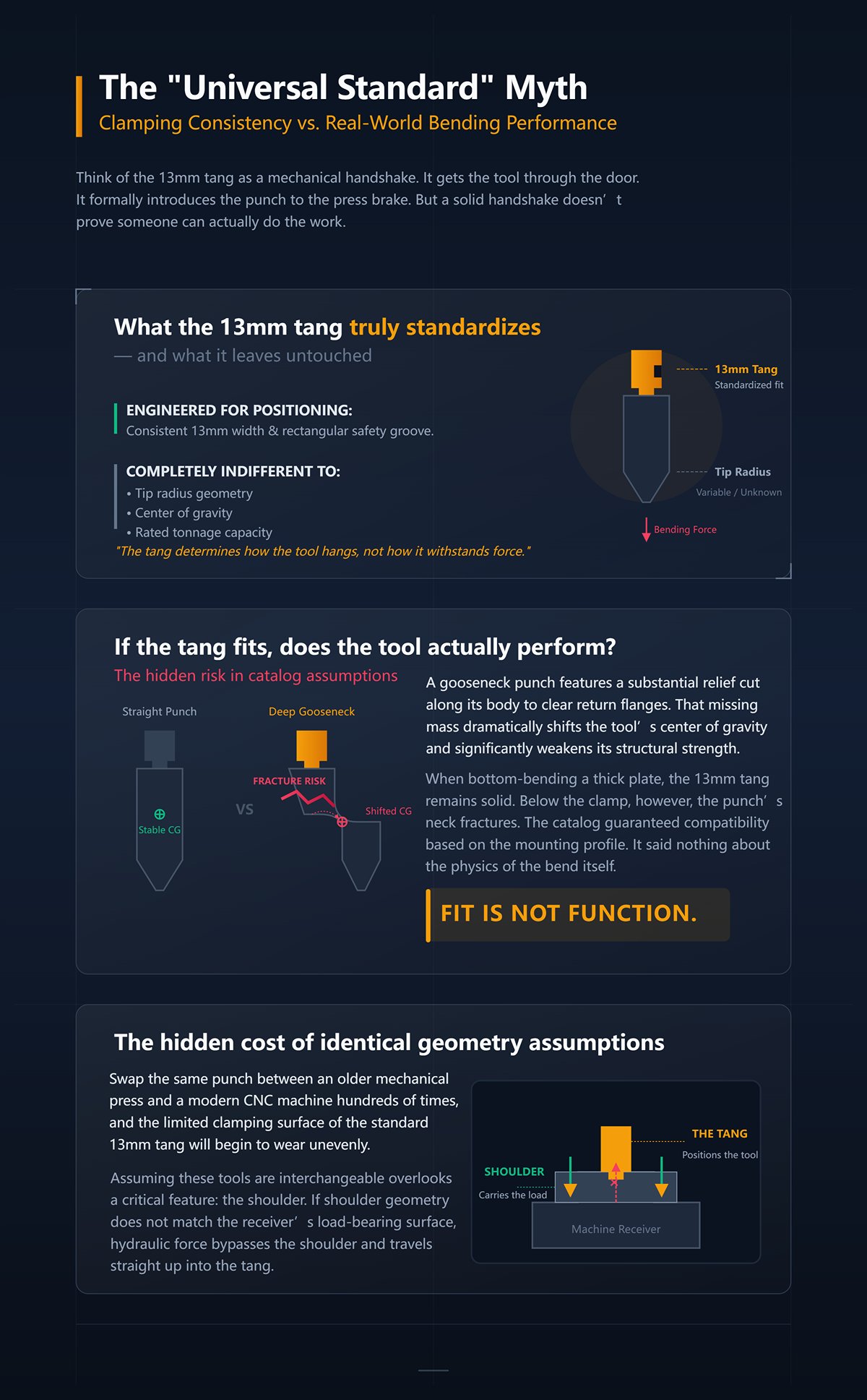
Think of the 13mm tang as a mechanical handshake. It gets the tool through the door. It formally introduces the punch to the press brake. But a solid handshake doesn’t prove someone can actually do the work.
Take a pair of calipers and measure the top of any European Precision–style punch. You’ll find a consistent 13-millimeter width and a precisely machined rectangular safety groove on the operator-facing side. That geometry was engineered for one purpose: to allow quick-clamp systems to secure the tool, pull it firmly against the load-bearing shoulder, and prevent it from dropping when the clamp is released.
It’s an elegant solution to a positioning problem.
On paper, the logic seems sound: if the tool is positioned correctly, the bending process should follow. In reality, the shop floor is far less forgiving. The tang determines how the tool hangs. It says nothing about how the tool withstands force. It standardizes the clamping interface, yet remains completely indifferent to the punch’s tip radius, center of gravity, or rated tonnage capacity.
If the tang only governs suspension, what absorbs the violence of the bend?
A purchasing manager orders a batch of deep gooseneck punches because they share the same 13mm tang as the straight punches the shop has relied on for years. The tang slides in seamlessly. The clamps lock without issue. But a gooseneck punch features a substantial relief cut along its body to clear return flanges.
That missing mass dramatically shifts the tool’s center of gravity and significantly weakens its structural strength.
When the operator steps on the pedal to bottom-bend a thick plate, the 13mm tang remains rock solid. Below the clamp, however, the punch’s neck fractures, sending shards skittering across the shop floor like shrapnel. The catalog guaranteed compatibility based on the mounting profile. It said nothing about the physics of the bend itself.
Shops comparing straight profiles to relief-cut designs such as Radius Press Brake Tooling or custom deep-return options quickly discover that identical tang geometry does not equal identical load paths.
Fit is not the same as function.
So does standardizing on a single tooling style actually ensure safety and repeatability?
Consider an older mechanical press brake retrofitted with modern quick clamps beside a state-of-the-art CNC hydraulic machine. On paper, both accept the same Amada-Promecam-style tooling. In practice, the older machine depends on manual wedge adjustments, while the CNC relies on hydraulic bladders to seat and secure the tool.
Even when using branded systems such as Amada Press Brake Tooling, clamping method and receiver condition can dramatically influence repeatability.
Swap the same punch between those two machines hundreds of times, and the limited clamping surface of the standard 13mm tang will begin to wear unevenly.
The punch that delivered perfect bends at 9 a.m. on the new machine can show a two-degree variation on the older press by noon. Assuming these tools are interchangeable overlooks a critical feature: the shoulder. The tang positions the tool; the shoulder carries the load. If the shoulder geometry does not precisely match the receiver’s load-bearing surface, hydraulic force bypasses the shoulder and travels straight up into the tang.
Force a positioning tang to act as a load-bearing shoulder, and you will ruin the tool, the clamp, or both.
Open any tooling catalog and you’ll find tonnage capacities presented in tidy, authoritative columns. A standard Euro punch may be rated at 29.2 kilonewtons per meter—about 10 short tons per foot. The numbers appear straightforward. You calculate the required bending force, compare it to the rating, and assume you’re operating safely.
But metal doesn’t read spec sheets.
Spec-sheet calculations assume perfect vertical alignment, nominal material thickness, and frictionless die entry. Real-world shop conditions involve warped hot-rolled plate, off-center loading, and abrasive mill scale. The 13mm tang ensures the tool hangs perfectly plumb in midair, but the instant the tip contacts steel, the punch’s geometry determines whether it withstands—or succumbs to—the violence of the bend.
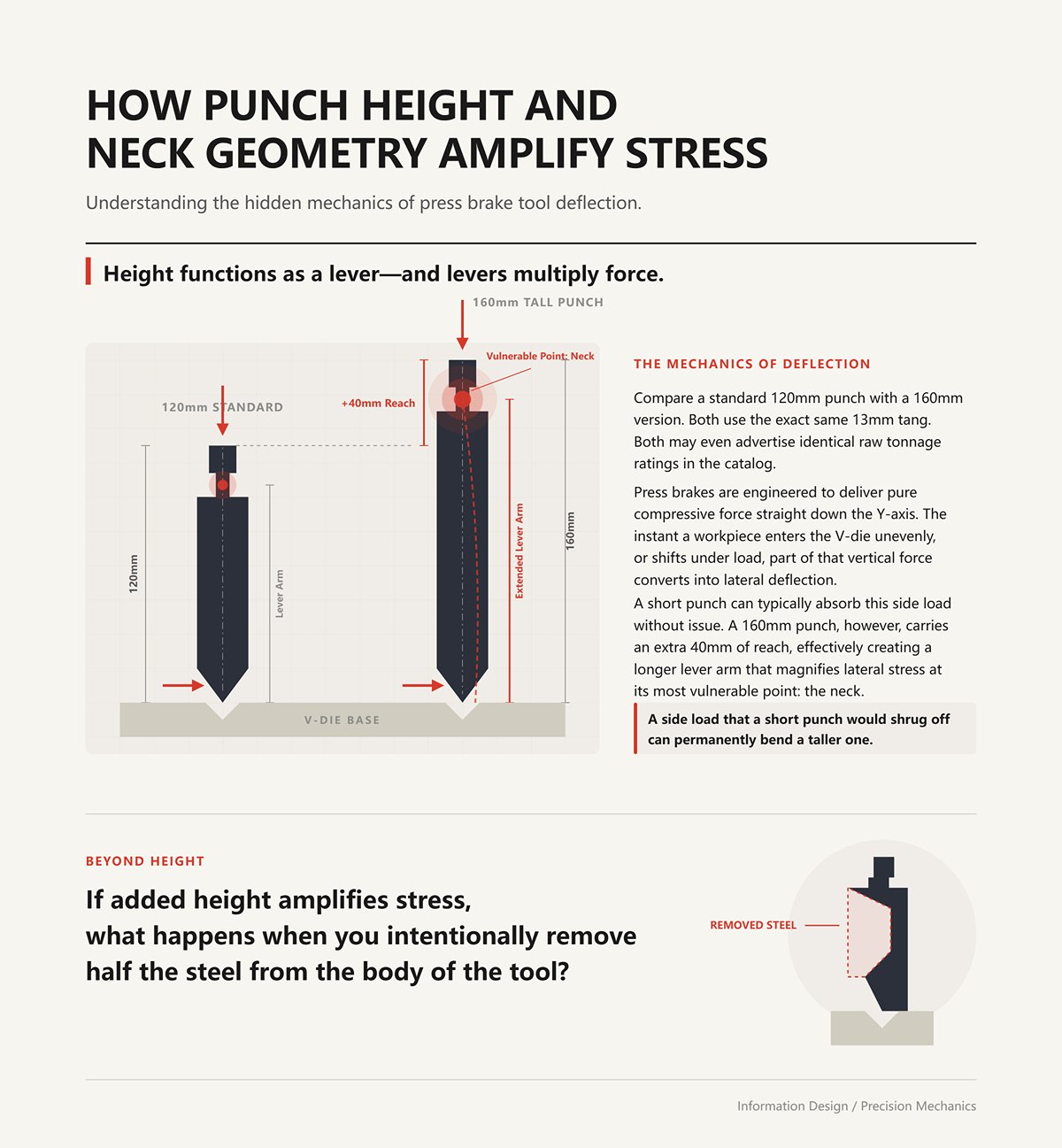
Compare a standard 120mm punch with a 160mm version. Both use the exact same 13mm tang. Both may even advertise identical raw tonnage ratings in the catalog. But when you bottom out due to a slight variation in material thickness, the 160mm punch responds in a completely different way.
Height functions as a lever—and levers multiply force.
Press brakes are engineered to deliver pure compressive force straight down the Y-axis. The instant a workpiece enters the V-die unevenly, or shifts under load, part of that vertical force converts into lateral deflection. A short punch can typically absorb this side load without issue. A 160mm punch, however, carries an extra 40mm of reach, effectively creating a longer lever arm that magnifies lateral stress at its most vulnerable point: the neck just beneath the clamping tang. A side load that a short punch would shrug off can permanently bend a taller one.
If added height amplifies stress, what happens when you intentionally remove half the steel from the body of the tool?
Consider a standard straight sash punch rated at 100 tons per meter. Now compare it to a deep gooseneck punch designed to clear a 4-inch return flange. The tang is identical, but the gooseneck features a substantial relief cut through its body.
That missing material fundamentally alters the load path.
Instead of hydraulic force traveling directly down the spine of the tool into the tip, it must detour around the relief cut. What should be a purely compressive load is transformed into a bending moment concentrated at the curve of the neck. A catalog may rate a gooseneck punch at 50 tons, but real-world shop conditions show that an off-center load during a deep return bend can fracture that neck at just 35 tons. When the operator presses the pedal, the 13mm tang remains locked firmly in the clamp—but below the shoulder, the neck can snap, sending broken tips across the shop floor like shrapnel.
Rule: Never rely on machine capacity to justify a tool’s survival.
| Aspect | Straight Punch | Gooseneck Punch |
|---|---|---|
| Rated Capacity | 100 tons per meter | Catalog rating: 50 tons |
| Design Feature | Straight sash design | Deep gooseneck with substantial relief cut to clear 4-inch return flange |
| Material Structure | Full body material maintains direct load path | Significant material removed, altering load path |
| Load Path | Hydraulic force travels directly down the spine into the tip (pure compression) | Force detours around relief cut, creating a bending moment at the neck curve |
| Real-World Performance | Typically performs close to rated capacity | Off-center load during deep return bend can cause fracture at 35 tons |
| Failure Risk | Lower risk under proper loading | Neck can snap below the shoulder while tang remains locked, potentially ejecting broken tips |
| Key Insight | Machine capacity often aligns with tool strength | Machine capacity does not guarantee tool survival due to structural weakness |
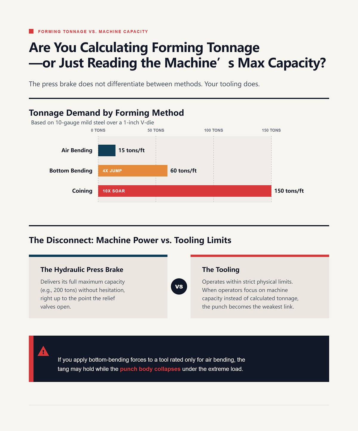
Air bending 10-gauge mild steel over a 1-inch V-die requires roughly 15 tons per foot. If an operator switches to bottom bending to achieve a tighter radius, the tonnage demand jumps to about 60 tons per foot. Attempt to coin the same part, and the required force can soar to 150 tons per foot.
The press brake does not differentiate between these methods.
A 200-ton hydraulic press brake will deliver its full 200 tons without hesitation—right up to the point the relief valves open. The tooling, however, operates within strict physical limits. When operators focus on the machine’s maximum capacity instead of calculating the actual tonnage required for a specific forming method, the punch becomes the weakest link in the hydraulic system. You may have the most robust clamping mechanism available, but if you apply bottom-bending forces to a tool rated only for air bending, the tang may hold while the punch body collapses under the load.
Understanding the structural limits of your complete Press Brake Toolings library—not just the machine rating—is what separates predictable production from catastrophic failure.
You may have the most robust clamping mechanism available, but if you apply bottom-bending forces to a tool rated only for air bending, the tang may hold while the punch body collapses under the load.
Mill standards permit up to a 10% thickness variation in conventional hot-rolled steel plate. On 16-gauge sheet, that 10% amounts to only a few thousandths of an inch—essentially negligible. On 1/4-inch plate, however, the same 10% tolerance adds 0.025 inches of solid steel at the pinch point.
Tonnage ratings are based on nominal material thickness and standard tensile strength assumptions.
In practice, steel mills frequently ship plate on the high side of the thickness range—or material that measures 15,000 psi above nominal tensile strength. When you drive a punch rated for 50 tons into plate that is both thicker and harder than spec, the required forming force rises dramatically. The tool does not wear out gradually; it fails abruptly, often by shearing. A “safe” rating on paper is only as dependable as the consistency of the material running through your press brake.
Even if the main body of the punch survives these hidden tonnage surges, what happens to the microscopic geometry at the tip—the very edge doing the work against the metal?
A brand-new, laser-hardened punch arrives at your dock stamped HRC 62 on the crate. You load it into the ram. The hydraulic clamp locks into place.
But that reassuring click can be deceiving.
That reassuring click tells you the tool is seated correctly—but it says nothing about whether it will survive the job. Spec sheets love to promise that extreme surface hardness guarantees superior wear resistance, slicing through abrasive mill scale bend after bend. On the shop floor, however, hardness simply means resistance to surface wear; it does not equal structural strength.
Manufacturers such as Jeelix emphasize selective hardening strategies—pairing a hardened working tip with a tougher core—to balance wear resistance and shock absorption in demanding environments.
When you drive an HRC 62 punch into heavy plate, the surface may resist abrasion, but the tool’s core must withstand immense compressive force. If the manufacturer hardened the steel all the way through in pursuit of a marketing benchmark, the tool loses the ductility required to flex under load. The tip won’t gradually wear—it will fracture, snapping like a glass rod and sending hardened steel fragments across the floor. A true precision punch pairs a selectively hardened tip (HRC 60+) to combat friction with a tempered, ductile core (around HRC 45) that absorbs shock. Rule: Hardness without underlying toughness is just glass waiting to shatter.
If the tool’s metallurgy survives the hit, what happens to the bend’s geometry?
Two punches sit on the tooling rack, both with the same 13 mm tang. One features a 1 mm tip radius; the other, a 2 mm radius. When aiming for a tighter bend, most operators instinctively reach for the 1 mm punch. Yet the older press brake relies on manual wedge adjustments, while the modern CNC machine uses hydraulic clamping systems to seat the tool—and in air bending, neither system factors in the punch tip radius.
In air bending, the part’s inside radius is determined solely by the V-die opening. For mild steel, it naturally forms at approximately 16 to 20 percent of the die width.
Bend over a 16 mm V-die, and the natural inside radius will be about 2.6 mm—whether you use a 1 mm or 2 mm punch. When the punch radius falls below the critical threshold of 63 percent of the material thickness, the process stops being a bend and becomes a crease. The punch behaves like a dull guillotine, cutting permanent stress fractures into the inside of the bend line. Choosing the sharpest available radius does not deliver precision; it produces a part with built-in structural weakness.
But if an overly sharp tip behaves like a blade, what happens when the punch radius is too large?
Bending half-inch high-strength steel plate completely rewrites the playbook. Instinct says a sharper tip will help drive the stubborn metal into shape. Physics says otherwise. To spread the immense stress and keep the outer radius from tearing, you need a large-radius punch—often three times the material thickness (3T).
But that solution hides a serious mechanical trap.
If you select a 10 mm radius punch while your V-die opening produces a natural inside radius of 8 mm, the punch is physically larger than the bend it’s meant to form. You’re no longer air bending. The punch is forced to coin its oversized profile into the sheet, overriding every standard tonnage calculation. The required force climbs exponentially. A bend that should require 40 tons can suddenly demand 120—stalling the hydraulics or permanently deflecting the ram. A sharp punch concentrates force; an oversized punch radius compels the machine to forge the metal rather than bend it.
So how do we reconcile the microscopic hardness at the punch tip with the macro geometry of the die to avoid this outcome?
Bend radius does not increase linearly with material thickness. Sheet metal under 6 mm typically bends at roughly a 1:1 ratio with its thickness. Move beyond 12 mm plate, and the required inside radius jumps to two or even three times the material thickness.
As thickness increases, the underlying math changes dramatically.
Standard V-die ratios—where 1:8 is ideal and 1:4 is the absolute minimum—determine how the load is distributed. When you drive a standard HRC 60 punch with a tight radius into a wide V-die while bending thick plate, the localized pressure at the punch tip becomes extreme. The die opening is wide, the material is thick, and the punch tip is confronting the full yield strength of the steel across a fraction of a millimeter. Even with a tough core, that compressive force can physically flatten a tight-radius tip. The tool mushrooms. Precision is lost—not because the 13 mm tang slipped, but because the tip deformed under a mathematically mismatched load. Rule: Never specify a punch radius without first calculating the natural radius produced by your V-die.
If you routinely bend variable thicknesses or high-tensile materials, exploring reinforced geometries or Special Press Brake Tooling designed for extreme load paths can prevent premature tip deformation.
The tool mushrooms. Precision is lost—not because the 13 mm tang slipped, but because the tip deformed under a mathematically mismatched load. Rule: Never specify a punch radius without first calculating the natural radius produced by your V-die.
Once the tool geometry is properly matched to the die, the next question is whether the machine’s receiver can actually withstand the tonnage you’ve calculated.
In 1977, the first CNC patent for press brakes entered the market, promising a new era of repeatability. For the first time, a controller could command ram stroke depth with micron-level precision. Yet that digital breakthrough exposed a significant blind spot on the shop floor. The CNC governs ram travel, operating on assumptions about tonnage and tool alignment beneath it. What it cannot see—or correct—is the mechanical interface between the punch tang and the machine’s receiver. You might purchase a Euro punch precision-ground to ±0.0005 inches, but secure it in a worn or poorly machined receiver and that tolerance disappears instantly. The receiver is the physical intermediary—the component that translates raw machine force into the refined geometry of the tool.
Components such as the Press Brake Clamping system and the underlying Press Brake Die Holder ultimately determine whether theoretical precision translates into real-world repeatability.
You might purchase a Euro punch precision-ground to ±0.0005 inches, but secure it in a worn or poorly machined receiver and that tolerance disappears instantly. The receiver is the physical intermediary—the component that translates raw machine force into the refined geometry of the tool.
If the receiver cannot hold the tool perfectly centered under load, what value does a flawlessly ground punch really provide?
The Euro tang incorporates a rectangular safety groove on the operator-facing side, engineered to engage a locking pin. On paper, this groove ensures the tool seats perfectly and self-aligns every time the clamp closes. In practice, however, the way that clamp actuates has a direct impact on your bend angle.
A hydraulic clamp engages all at once.
Pressurized bladders expand along the full length of the ram, driving hardened pins into the tool’s groove with consistent force and seating the punch flush against the load-bearing surface. By contrast, older mechanical receivers depend on manual set screws and wedge adjustments. When an operator tightens a series of mechanical wedges across a 10-foot bed, variability is inevitable. One wedge may receive 50 foot-pounds of torque; the next, 70. That uneven clamping force introduces a subtle bow into the tooling line before the ram ever contacts the material. The punch may be secure—but it is no longer straight.
Rule: A precision tool secured in an unevenly torqued receiver becomes a distorted tool.
How does this mechanical inconsistency compound when we move away from solid, full-length punches?
Forming a complex three-meter box profile often means assembling ten separate 300 mm punch segments. Modular tooling is promoted as the ultimate quick-change solution—no forklift required to wrestle a massive, one-piece punch into place. But dividing a single tool into ten sections also introduces ten independent mating interfaces inside the receiver.
Each segment comes with its own minute dimensional variation.
If hydraulic clamping pressure drops by just a few bar at the far end of the ram, or if a mechanical wedge is even slightly backed off, those segments will not seat with equal upward force. As the ram descends into the sheet, the looser segments are driven upward into microscopic gaps within the receiver. The result is a “zippered” bend line, where the inside radius visibly steps up and down along the part’s length. In other words, the quick-change convenience of segmented punches can turn minor receiver inconsistencies into a severe tolerance stack-up.
So what happens when those precisely ground segments are inserted into a receiver that has spent a decade battling high-tensile steel?
After 10,000 bottoming cycles on heavy plate, the internal contact surfaces of a standard receiver begin to deform. The constant upward and rearward thrust from the punch gradually wears down the receiver’s vertical face.
A gap of only 0.5 mm is enough to wipe out your precision.
Spec sheets suggest that high clamping pressure can compensate for minor wear. In reality, clamping force cannot grip metal that no longer exists. A “standard” Euro punch may feel solid when locked into a worn holder. But the instant the punch tip contacts the material, tonnage forces the tool to pivot backward into that 0.5 mm void. The tip shifts off center. Your intended 90-degree bend becomes 91.5 degrees on the left and 89 degrees on the right. You can spend hours adjusting the CNC crowning system without realizing the punch is physically tilting inside the clamp under load. Rule: No amount of software compensation can correct a tool that moves during the bend.
If the holder is compromised, can you simply bolt a new precision receiver onto an aging machine frame?
A shop running a 1,500-ton press brake from the 1970s will eventually look to modernize by retrofitting modular Euro-style receivers onto the original ram. The catalogs make it sound simple: bolt on a new clamping system and instantly elevate the machine’s accuracy to contemporary standards.
But the underlying structure is already compromised.
That ram was machined decades before the Euro standard even existed, to entirely different parallelism tolerances. When you fasten a perfectly straight, modern receiver onto an aging ram with even slight crowning or bellies, the mounting bolts become the weakest link in the system. Under the extreme tonnage required for thick plate, the conflicting geometries start working against each other. The bolted receiver flexes, introducing gradual accuracy drift that varies depending on where the part sits along the bed. You upgraded the clamp—but ignored the foundation.
If the receiver itself becomes the limiting factor for tonnage and stability, how do you tool up for heavy plate that pushes beyond the Euro standard’s structural ceiling?
Asking a surgical scalpel to split firewood is a category mistake. It’s sharp. It’s precise. But it has no backbone for blunt-force impact. That’s exactly what happens when you expect a standard Euro 13mm tang to bend half-inch plate.
Spec sheets often blur this distinction. They cite the maximum theoretical tonnage a hardened Euro punch can withstand under controlled laboratory conditions and declare it suitable for heavy plate. But on the shop floor, success isn’t measured in theory—it’s measured in survival.
The 13mm tang is essentially a mechanical handshake. It secures the tool quickly and ensures fast changeovers. But once the ram drives that punch into thick steel, the handshake ends and raw physics takes over. So what actually happens to that carefully engineered precision geometry when we stop gently forming metal and start crushing it?
Air bending is a controlled negotiation between tool and material. The punch presses the sheet into the V-die just deep enough to achieve the target angle, relying on CNC depth control rather than physical contact at full force. In this context, the Euro standard performs beautifully. Its offset geometry—where the punch tip sits forward of the tang—makes complex return bends possible without the sheet striking the ram.
Bottoming, by contrast, is a bar fight.
When you bottom or coin heavy material, you drive the punch tip completely into the sheet, imprinting the die’s exact angle into the metal. In the final millimeter of stroke, tonnage rises exponentially. Because the Euro punch tip is offset from the centerline of the 13mm tang, that immense upward force creates a severe bending moment. The load does not travel straight up into the ram—it tries to snap the punch backward. I have seen 13mm tangs shear off entirely, leaving a fractured punch tip lodged in the die and a scarred receiver above it. Rule: Offset geometry cannot withstand direct, dead-center trauma. If heavy tonnage makes failure inevitable, at what thickness should you stop trusting it?
On paper, spec sheets suggest you can run Euro tooling up to its rated tonnage limit regardless of material thickness. On the shop floor, high-tensile heavy plate exposes the tang’s structural weakness long before the press brake reaches its hydraulic ceiling. The tipping point typically arrives around 1/4 inch (6mm) for high-strength steel, or about 3/8 inch for mild steel.
This is the moment you walk away from the tang.
American-style tooling—or heavy-duty New Standard hybrid systems—eliminates the narrow offset tang altogether. Instead, it uses a wide, centered load-bearing surface that transfers force directly into the ram. There is no bending moment; the load travels straight through the backbone of the tool. If you routinely bend half-inch plate, keeping standard Euro tooling in the machine means you are always one poor setup away from a catastrophic failure. You are sacrificing structural integrity for a clamping method designed for lighter-gauge work. But if American tooling offers clear structural advantages for heavy plate, how much production time are you losing to the effort of bolting it into place?
If you are evaluating whether your current tooling library can safely transition between thin-gauge enclosures and heavy plate fabrication, reviewing detailed product data or requesting technical guidance can prevent costly mistakes—simply Contact us to discuss your specific tonnage and material requirements.
Euro tooling dominates the setup discussion because the 13mm tang lets an operator drop a punch into the clamp, press a button, and move on. American tooling traditionally requires sliding punches in from the end of the bed and tightening individual bolts. In a high-mix environment running twenty different thin-gauge enclosure setups a day, the Euro system can save hours of labor.
Setup speed means nothing if the tool cannot bend the part.
When a mixed-material shop lands a heavy plate job, operators are often tempted to game the system. They flip Euro punches using expensive, dedicated offset holders, or slow the machine’s approach speed to a crawl to avoid snapping a tang. That caution quietly adds hours to the production run. The real cost of rigidity isn’t the twenty minutes it takes to bolt in a heavy-duty American punch. The real cost is the scrapped half-inch plate, the shattered Euro punches, and the spindle downtime that comes from forcing a precision instrument to perform like a sledgehammer. Rule: Never trade the rigidity required to bend the metal for the convenience of loading the tool. Once you accept that heavy plate demands heavy-duty geometry, the next question is practical: how do you build a tooling library that delivers that strength without burying your shop in redundant systems?
The hydraulic clamp snaps into place. That satisfying click is deceptive. It confirms the punch is seated, but says nothing about whether the tool’s internal structure can withstand the violence of the stroke that follows. Treating Euro tooling as a universally interchangeable commodity simply because it shares a 13mm tang is how shops end up digging shattered tool steel out of a destroyed die. The tang is merely a mechanical handshake—it gets the tool in the door. To build a tooling library that won’t bankrupt your operation with catastrophic failures, you have to stop buying for the clamp and start buying for the metal. So where should this filtering process begin—before a single purchase order is issued?
Spec sheets present a maximum static load calculated under controlled, laboratory conditions. The shop floor is different. It delivers dynamic, exponential force spikes the instant a punch begins to bottom out high-tensile steel. If you open a tooling catalog first, you’ll almost always choose a punch based on its profile instead of its structural backbone. Start with your most demanding bend. Calculate the required tonnage per meter for that exact material thickness and V-die opening, then map that force against the tool’s offset geometry.
If your application requires 80 tons per meter and the Euro punch is rated for 100, you’re already operating in the danger zone.
The offset geometry of a standard Euro punch generates a significant bending moment under heavy loads. In practical terms, that 100-ton rating deteriorates quickly if the applied force is even slightly off vertical. When you drive a tool to its theoretical maximum, the tang doesn’t gradually fatigue—it can shear off outright. Rule: Purchase tooling rated for at least 1.5× your highest calculated tonnage spike, not your average air-bend load. But even with the tonnage math dialed in, how do you confirm that your press brake can transmit that force without compromising the tool holder?
The 13 mm Euro tang includes a rectangular safety groove engineered to lock the tool securely and ensure repeatable positioning. However, older machines rely on manual wedge systems, while modern CNC brakes use hydraulic clamping to seat the tool. If your receiver shows wear, bell-mouthed clamp plates, or hydraulic pins that fail to engage the groove depth consistently, that “secure” tang becomes little more than a false assurance.
You are not matching a tool to a theoretical Euro specification—you are matching it to the physical condition of your actual receiver. A precisely machined tang installed in a compromised clamp will shift under load, displacing the centerline force and instantly distorting your bend angle. Rule: Never rely on a precision tang inside a worn receiver. If the tonnage is correct and the clamping system is sound, what ultimately determines whether a punch tip endures a thousand cycles—or fractures on day three?
Hardness is always a balancing act between wear resistance and brittleness. Tool catalogs love to promote 60 HRC through-hardened punches, framing maximum hardness as the ultimate indicator of quality. But a fully hardened, offset Euro punch subjected to shock loads from mixed gauges of hot-rolled steel won’t simply wear over time—it can fracture catastrophically.
If you’re running high-frequency air bends on clean stainless steel, you absolutely need extreme surface hardness to prevent galling and tip wear. But if your shop occasionally coins material or wrestles with heavy plate, you need a tool with a hardened working surface and a tougher, more ductile core—one that can absorb blunt-force shock without fracturing. The rule is simple: match the metallurgy to the violence of the bend, not to the claims printed on the box. When you align required tonnage, true receiver fit, and application-specific metallurgy, how does that reshape your entire purchasing philosophy?
You stop viewing tools as generic shapes that merely happen to fit your machine. Instead, you see them as sequence-specific consumables—engineered to overcome defined material limits. The 13 mm tang is no longer the deciding factor; it’s simply the minimum requirement for entry.
This shift in perspective transforms the way you walk the shop floor. You no longer ask operators why a “standard” tool failed on a routine job, because you recognize that the tool was likely under-rated for the tonnage, mismatched to a worn receiver, or too brittle for the shock load involved. A true tooling library isn’t built by collecting profiles that share a common tang. It’s built by auditing the physics of your daily production and investing in the precise geometry, hardness, and load capacity required to confront the metal—and win. The next time you open a catalog, ignore the tang altogether. Focus on the spine, the core, and the load limits. When the ram comes down, the press brake doesn’t care which standard you bought.
 العربية
 বাংলা
বাংলা
 Български
 Čeština
 Dansk
Dansk
 Nederlands
 Suomi
Suomi
 Français
 Deutsch
 Ελληνικά
 עִבְרִית
 हिन्दी
 Magyar
 Bahasa Indonesia
 Italiano
 日本語
日本語
 Қазақ тілі
 한국어
한국어
 Bahasa Melayu
 Norsk bokmål
 فارسی
فارسی
 Polski
 Português
 Română
 Русский
 Српски језик
 Slovenčina
 Español de México
 Español
 Kiswahili
 Svenska
 Tagalog
 தமிழ்
தமிழ்
 ไทย
ไทย
 Türkçe
 Українська
 اردو
اردو
 Tiếng Việt
 简体中文
简体中文
 香港中文
香港中文
 繁體中文
繁體中文
