Showing all 5 results
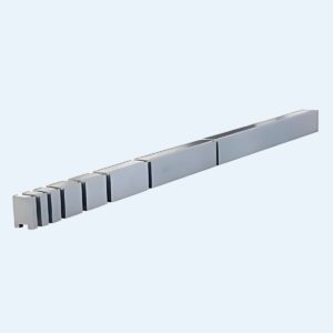
Radius Tool Holder, Radius Press Brake Tooling
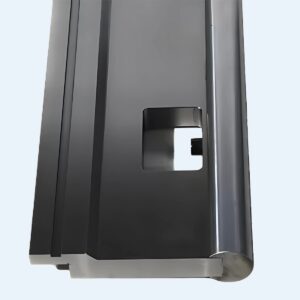
Radius Tool Holder, Radius Press Brake Tooling
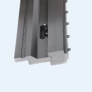
Radius Tool Holder, Radius Press Brake Tooling
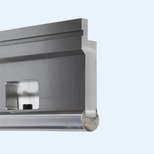
Radius Tool Holder, Radius Press Brake Tooling
Radius Tool Holder, Radius Press Brake Tooling
I watched a good lathe sing itself into scrap over a 0.8 mm nose radius swap.
Same material. Same program. Same RPM. The only thing that changed was the insert — dropped into the same “standard” holder we’d been using for years. Fifteen minutes later the finish looked like corduroy and the operator was blaming feeds and speeds.
That’s when I stopped letting guys call a holder “just a clamp.” The right toolholder is a precision interface, a concept well understood by specialists in tooling systems like Jeelix, where the geometry defines performance.
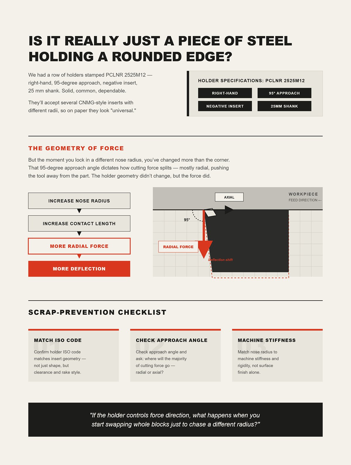
We had a row of holders stamped PCLNR 2525M12 — right-hand, 95-degree approach, negative insert, 25 mm shank. Solid, common, dependable. They’ll accept several CNMG-style inserts with different radii, so on paper they look “universal.”
But the moment you lock in a different nose radius, you’ve changed more than the corner.
That 95-degree approach angle dictates how cutting force splits — mostly radial, pushing the tool away from the part. Increase the nose radius and you increase contact length. More contact length means more radial force. More radial force means more deflection. The holder geometry didn’t change, but the force direction and magnitude did.
So what exactly stayed universal? This is a critical question not just for turning, but for any forming process. The principles of force direction and geometry compatibility are equally vital in sheet metal work, where selecting the correct Standard Press Brake Tooling or brand-specific tooling like Amada Press Brake Tooling or Wila Press Brake Tooling is foundational to preventing deflection and achieving precision.
Scrap-Prevention Checklist
Confirm holder ISO code matches insert geometry — not just shape, but clearance and rake style.
Check approach angle and ask: where will the majority of force go — radial or axial?
Match nose radius to machine stiffness, not surface finish alone.
If the holder controls force direction, what happens when you start swapping whole blocks just to chase a different radius?
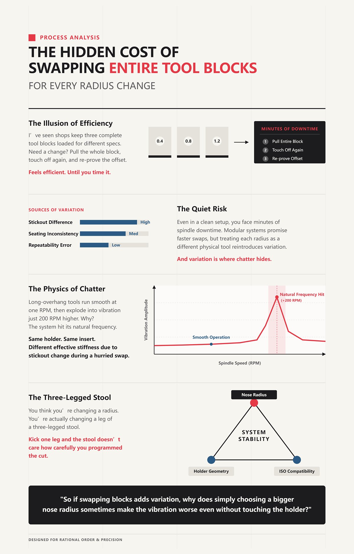
I’ve seen shops keep three complete tool blocks loaded: 0.4 mm, 0.8 mm, 1.2 mm. Need a different finish spec? Pull the whole block, touch off again, re-prove the offset.
Feels efficient.
Until you time it.
Even in a clean setup, you’re looking at minutes of spindle downtime, plus the quiet risk — slightly different stickout, slightly different seating, slightly different repeatability. Modular systems promise faster swaps, but if you treat each radius as a different physical tool instead of part of a system, you’re still reintroducing variation every time.
And variation is where chatter hides. This challenge of fast, repeatable changeover while maintaining rigidity is a core focus for advanced tooling solutions, including those designed for presses from manufacturers like Trumpf Press Brake Tooling.
I’ve watched long-overhang tools run smooth at one RPM, then explode into vibration 200 RPM higher because the system hit its natural frequency. Same holder. Same insert. Different effective stiffness due to stickout change during a hurried swap.
You think you’re changing a radius.
You’re actually changing a leg of a three-legged stool: holder geometry, ISO compatibility, nose radius.
Kick one leg and the stool doesn’t care how carefully you programmed the cut.
So if swapping blocks adds variation, why does simply choosing a bigger nose radius sometimes make the vibration worse even without touching the holder?
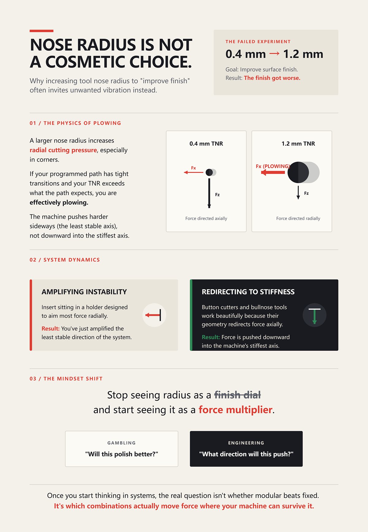
A customer once insisted on moving from 0.4 mm to 1.2 mm to “improve finish.”
The finish got worse.
Here’s why: a larger nose radius increases radial cutting pressure, especially in corners. If your programmed path has tight transitions and your tool nose radius (TNR) exceeds what the path expects, you’re effectively plowing. The machine pushes harder sideways, not downward into the stiffest axis.
Now imagine that insert sitting in a holder designed to aim most force radially. You’ve just amplified the least stable direction of the system.
It’s not that large radii are bad. Button cutters and bullnose tools work beautifully because their geometry redirects force axially — into stiffness. The holder and insert are designed as a pair. Similarly, in bending, specialized Radius Press Brake Tooling is engineered to manage the unique forces of larger arcs without inducing deflection or springback.
That’s the shift I want you to make: stop seeing radius as a finish dial and start seeing it as a force multiplier that either cooperates with holder geometry or fights it.
When you look at a radius change and immediately think, “What direction will this push my system?” instead of “Will this polish better?” — you’ve stopped gambling and started engineering.
And once you start thinking in systems, the real question isn’t whether modular beats fixed.
It’s which combinations actually move force where your machine can survive it.
I watched a BMT turret holder repeat within a couple tenths on one station and miss by nearly a thou on the next after a quick radius-module swap — same machine, same operator, different interface stack.
That’s the part nobody advertises when they pitch modular radius holders as the cure for chatter and setup time. On paper, modular wins: change the head, keep the base, save time. In practice, the interface becomes another spring in your force system. Every joint — turret face to holder, holder to modular pocket, pocket to insert — has compliance. Under light finishing cuts, you’ll never notice. Under a heavy CNMG rougher pushing mostly radially out of a 95° approach holder, you will.
A fixed-radius solid tool has fewer joints. Fewer joints mean fewer places for micro-movement when cutting force peaks at the nose. But it also means every radius change is a physical tool change, with its own repeatability story. The same philosophy applies to press brake setups; a solid Press Brake Die Holder provides a rigid foundation, but modular systems offer flexibility for complex jobs.
So the showdown isn’t modular versus fixed.
It’s interface stiffness versus cutting-force direction — and whether the radius you chose multiplies the weak axis of that stack or feeds the strong one.
Which brings us to money, because nobody argues tooling philosophy until scrap shows up on the cost sheet.
I scrapped a batch of 4140 shafts because a “cost-saving” insert didn’t seat perfectly in a modular radius head — it rocked just enough to print chatter at the shoulder blend.
Let’s run a clean hypothetical. A dedicated solid-radius form tool costs more up front and needs regrinding when it wears. That means pull it, send it out, wait days, maybe weeks. A modular system with replaceable inserts isolates wear to the insert. Swap it in minutes. No shipping. No geometry drift from repeated grinds.
On paper, modular crushes regrind economics.
Until the insert isn’t a perfect ISO match to the pocket.
A holder stamped PCLNR 2525M12 expects a specific insert geometry: negative rake, correct clearance, correct thickness, correct nose spec. If you drop in a “close enough” variant — same shape code, slightly different tolerance class or edge prep — the insert can micro-shift under load. That shift increases radial compliance. Radial compliance increases chatter risk. Chatter ruins finish. Ruined finish kills parts.
What did you save on regrinding if you scrap ten shafts? For unique or demanding applications, sometimes the economics only work with purpose-built Special Press Brake Tooling, where the upfront cost is justified by flawless repeatability and zero scrap.
Economics in tooling only work when the insert, pocket, and holder geometry form a rigid triangle. Break one leg and the three-legged stool doesn’t wobble politely — it collapses under load.
And if modular wins on insert cost and lead time, where does it actually win the clock on the shop floor?
I’ve seen a punch press crew swap a modular radius segment in under five minutes while the old-school solid tool sat on a bench waiting for a forklift.
In high-mix environments, modular systems shine because the base stays qualified. On a CNC lathe with a turret, if your modular head repeats axially within a couple tenths and you’ve controlled stickout, you can swap a radius cartridge without re-indicating the entire block. That’s real time saved.
But here’s the catch: not all interfaces repeat equally.
Some BMT-style holders prioritize quick clamping over ultimate face contact. A dual-contact spindle system like HSK pulls on both taper and face, resisting axial pull and bell-mouthing at high speed. That face contact increases rigidity in the spindle axis. If your cut loads axially — think button-style geometry pushing force down the spindle — modular in an HSK system can actually outperform a basic steep-taper fixed shank. This principle of enhancing rigidity through interface design is also key in systems like Press Brake Crowning and Press Brake Clamping to ensure consistent force distribution.
Button cutters and bullnose tools work beautifully because their geometry redirects force axially — into stiffness.
Now imagine that insert sitting in a holder designed to aim most force radially. Fast changeover doesn’t fix that physics. It just lets you get back to vibrating sooner.
So modular absolutely slashes downtime in the right machine architecture. But if the interface stiffness doesn’t match the force vector your radius generates, you’ve traded setup time for dynamic instability.
And when the cut gets heavy, the marketing claims get quiet.
| Aspect | CNC Turret (Modular System) | Punch Press (Modular vs. Solid Tool) |
|---|---|---|
| Downtime Example | Radius cartridge swapped without re-indicating entire block if axial repeatability is controlled | Modular radius segment swapped in under five minutes; solid tool may require forklift and longer changeover |
| High-Mix Advantage | Base remains qualified, reducing setup time between jobs | Quick segment swaps improve flexibility in varied production runs |
| Interface Repeatability | Depends on holder design; not all interfaces repeat equally | Less sensitive to spindle interface, but still dependent on proper seating and alignment |
| Clamping & Contact Design | BMT prioritizes quick clamping; HSK dual-contact (taper + face) improves axial rigidity | Typically simpler clamping; rigidity varies by tool design |
| Rigidity Under Axial Load | HSK resists axial pull and bell-mouthing; can outperform basic steep-taper shanks | Performance depends on press structure; modularity mainly impacts changeover time |
| Force Direction & Tool Geometry | Button and bullnose cutters redirect force axially into spindle stiffness | Tool geometry affects force distribution but less influenced by spindle interface |
| Risk Factor | Mismatch between interface stiffness and force vector can cause vibration | Fast changeover does not compensate for poor force alignment or rigidity |
| Heavy Cutting Conditions | Marketing claims fade if interface lacks stiffness under load | Modular benefits remain in speed, but rigidity limits still apply |
I watched a modular roughing head walk out of a cut in 4340 at 3 mm depth while a boring, solid shank tool right beside it held steady at the same feed.
Heavy cuts magnify compliance. A large nose radius increases contact length. More contact length means higher radial force if the approach angle is near 95°. Radial force pushes the tool away from the part — the least stiff direction on most lathes.
A solid shank tool with a single-piece body has one less bending interface than a modular head stacked on a base. Under high radial load, that matters. Deflection is proportional to force and inversely proportional to stiffness. Increase force with a bigger radius, decrease stiffness with extra joints, and you’ve just amplified chatter mathematically.
But flip the geometry.
Use a holder and insert combination that shifts force axially — lower approach angle, round insert in a pocket designed to support it, machine with strong spindle bearings and face contact. Suddenly the modular system isn’t the weak link. The force is traveling into the machine’s strongest structural path. Exploring a comprehensive range of Press Brake Toolings can reveal how different designs manage these force pathways for optimal rigidity.
That’s the real comparison.
Solid shanks win when radial load dominates and every micron of bending counts. Modular wins when its interface is rigid enough for the force direction you’ve engineered into the cut.
So before you swap fixed tools for modular radius holders chasing faster setups, ask the harder question:
Is this holder–insert–radius combination pushing force into my machine’s spine — or into its ribs?
I had a guy bump a finishing tool from 0.4 mm to 1.2 mm nose radius on a slant-bed lathe, same holder, same speeds, same depth — and the finish went from glass to washboard in one pass.
Nothing else changed.
So how do you know, in your own shop, whether that bigger arc is feeding your machine’s strong axis or hammering the weak one?
Start with the force picture. A larger nose radius increases contact length between insert and material. Longer contact means higher radial force if your approach angle is near 95° — and most general turning holders are right there. Radial force pushes the tool away from the part. On most lathes, that direction is less stiff than axial — you’re bending the holder, turret, and sometimes even the cross-slide stack.
If the machine sings louder when you increase depth of cut but quiets down when you reduce it — that’s radial compliance talking. If the sound changes more with feed adjustments than depth, you’re likely loading axially.
The paradox shows up because a bigger radius does improve theoretical surface finish. The scallop height shrinks. On paper, it’s cleaner.
But the moment your machine can’t support the added radial force, that smooth arc becomes a vibration amplifier. The insert doesn’t just cut; it flexes the system, stores energy, and releases it. That’s chatter.
And here’s the part that matters to the bigger argument: nose radius isn’t a finish parameter. It’s a force-direction decision that has to match holder geometry and machine stiffness.
The question isn’t “Is bigger smoother?”
It’s “Is bigger supported?”
A study I reviewed compared 0.2 mm, 0.4 mm, and 1.2 mm radii in controlled cuts — and the smallest radius delayed chatter onset the longest.
That’s backwards from what most of us were taught.
Sound energy jumped dramatically for the 0.4 mm and 1.2 mm tools once instability began, while the 0.2 mm radius held stable deeper into the test range. Why? Because increasing radius increases radial cutting force and cross-coupling between radial and axial vibrations. The system starts feeding its own oscillation.
Here’s where it gets interesting.
When depth of cut approached the size of the nose radius — say running near 1.0 mm depth with a 1.2 mm radius — instability tightened up. Cross-coupling intensified. Radial motion excited axial vibration and vice versa. Stability limits narrowed, not widened.
But in one case, peak-to-peak force actually dropped at a 1 mm depth after rising between 0.1–0.5 mm.
Unstable-stable chatter transition.
The system flipped modes.
That’s the tipping point in real terms: every machine–holder–radius stack has a depth where forces align just wrong and amplify vibration, then another depth where the dynamics shift and it calms down. If you’ve ever had a cut that screams at 0.3 mm but runs clean at 1.0 mm, you’ve seen it.
So how do you find your tipping point without sacrificing parts?
You change one variable at a time and watch force direction effects:
Increase depth while holding feed constant — does chatter scale linearly or spike suddenly?
Drop nose radius but keep depth — does stability improve immediately?
Shift approach angle — does the noise move or disappear?
That’s not guesswork. That’s mapping your machine’s weak axis.
Scrap-Prevention Checklist:
Match nose radius to a depth of cut that stays either well below or intentionally at a stable harmonic zone — never hovering near equal values blindly.
If chatter starts earlier with larger radius at light cuts, suspect radial compliance first.
Don’t chase finish with radius until you confirm the holder can support the added contact force.
Now the real question: if radial force is the villain, what in the holder actually decides whether it survives or folds?
I once watched a 0.079″ round insert scream in aluminum on a narrow, multi-directional turning holder — low SFM, light depth, didn’t matter. It squealed like a dry bearing.
Same insert, heavier pocket holder, noise gone.
The difference wasn’t the radius. It was sectional stiffness.
Round inserts — especially larger radii — spread force over a broad arc. That arc generates radial load across a wider contact zone. If the holder’s cross-section is thin or interrupted — think modular heads with narrow necks — bending stiffness drops fast. Deflection increases with force, and force increases with radius.
Deflection is proportional to force and inversely proportional to stiffness. That’s not philosophy. That’s beam theory.
An “arc-style” pocket that fully supports the insert along its curvature distributes load better than a flat-sided or partially supported seat. If the insert rocks even microscopically, dynamic radial compliance increases. The insert begins micro-shifting under load.
And when the insert shifts, the effective nose radius changes dynamically.
That’s when chatter stops being predictable.
Button cutters and bullnose tools work beautifully because their geometry redirects force axially — into stiffness.
Now imagine that insert sitting in a holder designed to aim most force radially.
You’ve just multiplied the weak axis. This concept of dedicated support for specific geometries extends to other fabrication areas, such as the specialized tooling found in Panel Bending Tools.
So when comparing arc-support versus sectional or narrow-neck holders, you’re really asking: which geometry resists bending under the specific radial force your chosen radius creates?
Three-legged stool again: holder geometry, nose radius, and ISO-compatible seating. Remove strength from one leg, and the arc you thought would smooth the cut becomes the lever that tips the whole system.
Which leads to the last lever in the system.
I’ve seen a 1.2 mm radius chatter at 0.3 mm depth but run clean at 1.0 mm, and that confuses machinists more than anything else.
Here’s what’s happening.
At shallow depths, only a portion of the nose engages. Force vectors concentrate near the leading edge, heavily radial in a 95° holder. As depth increases toward the radius value, the engagement angle shifts. The force vector rotates slightly. Cross-coupling grows — radial vibration excites axial motion.
That’s the danger zone.
But push deeper, and sometimes the contact patch stabilizes along a more constant arc. The force direction becomes more predictable. The system may land in a more stable lobe of its dynamic response.
This is why treating radius as a finish tweak fails. The relationship between depth and radius literally rotates your force vector in space.
If depth of cut is much smaller than radius, you’re amplifying radial load with minimal axial stabilization. If depth approaches radius, you risk cross-coupled chatter. If depth significantly exceeds radius in certain geometries, you may enter a more stable force distribution — or overload the holder entirely.
There is no universal “best” radius.
There is only a radius that matches:
The stiffness of your holder cross-section
The seating security defined by its ISO geometry
The depth of cut that keeps force flowing into the machine’s spine, not its ribs
And that sets up the next problem.
Because even if you choose the perfect radius for your machine’s stiffness and depth regime, it still fails if the insert doesn’t seat exactly as the holder’s ISO code intends.
So how precise does that compatibility really need to be before geometry starts lying to you?
I’ve watched a brand-new DNMG 150608 rock in a holder that was “close enough” on paper — chatter started at 0.25 mm depth, and the operator swore the pocket looked perfect.
It did look perfect. The insert sat flat. Clamp screw torqued. No daylight under the seat.
But under load, it shifted about a few microns — not visible, not measurable with a feeler — just enough that the cutting edge no longer met the work at the relief angle the holder was designed to present. That tiny rotation changed the force vector. Radial force increased. The weak axis lit up.
Here’s the hard answer to your question: seating error doesn’t have to be visible to distort force direction. A relief-angle mismatch of a few degrees — the difference between C (7°) and N (0°) in the ISO code — changes how the insert contacts the pocket wall and how load transfers into the holder. Once the insert stops bearing exactly where the designer intended, the force path bends. And when the force path bends, stability follows it.
You already mapped depth, radius, and holder stiffness. ISO geometry is the final leg of the stool.
If it’s short, the whole system tilts.
So what does “fits the pocket” actually mean in mechanical terms?
I once saw a guy drop a CNMG 120408 into a holder meant for CCMT 120408 because “the diamond’s the same.”
Same 80° shape. Same size. Different second letter.
That second letter is relief angle. N means 0°. C means 7° positive relief. That’s not cosmetic. That’s the angle that prevents the flank from rubbing.
A holder designed for positive inserts seats the insert against a pocket floor and side walls that assume relief clearance underneath. Put a 0° insert in there and the flank contacts where it shouldn’t. The insert doesn’t just sit wrong — it wedges differently under cutting load. Instead of transferring force cleanly into the back wall of the pocket, it creates a micro-pivot.
Now load it at a 95° entering angle. Radial force is already significant. That pivot becomes a hinge. The insert microscopically lifts at the nose. Effective nose radius changes dynamically. Finish goes from consistent to torn.
And here’s the part that costs you time: it might cut fine at 0.1 mm depth. At 0.4 mm, it sings. At 0.8 mm, it chips.
The operator starts chasing feeds and speeds.
But the instability started at the seat.
Scrap-Prevention Checklist:
Verify the first two ISO letters match the holder spec — shape and relief are non-negotiable.
Confirm the holder is designed for positive or negative geometry; never assume cross-compatibility.
If chatter appears only as depth increases, inspect seating contact patterns before touching feeds.
If relief angle mismatch can create a hinge under load, what happens when the approach angle itself fights the insert geometry?
A hydraulic fitting shop I worked with switched from an 80° CNMG to a 55° DNMG because the original toolholder couldn’t access an internal groove without interference.
They thought modular heads would fix it. They didn’t.
The real constraint was nose angle and how the holder presented it to the work. The 80° insert in that holder produced higher cutting forces and a broader engagement zone. Strong edge, yes. But more radial load. In a tight internal profile, that load pushed the insert into a deflection pattern the machine couldn’t damp.
Switching to 55° reduced contact width and altered the force vector. Not because 55° is “better,” but because it aligned the force direction with the holder’s stiffness and the machine’s spindle axis.
Now add relief to that picture.
A positive insert like DCMT (7° relief) reduces cutting force and radial pressure compared to a negative DNMG (0°). If you mount a negative insert in a holder designed to direct force axially — counting on lower radial load — you’ve just contradicted the design assumption. The entering angle may be pushing force toward the chuck, but the relief geometry is increasing contact pressure and radial reaction.
Force direction is a negotiation between:
Entering angle (holder geometry)
Relief angle (second ISO letter)
Nose angle (first ISO letter)
Ignore one, and the other two lie to you.
You don’t “tune” that with spindle speed. You correct it at the code level.
So when does mixing brands work — and when does it quietly start stretching your setup times?
I’ve run off-brand inserts in premium holders when supply chains got ugly. Some ran fine. Some made me question my sanity.
Here’s the difference.
If the insert matches ISO shape, relief, tolerance class, thickness, and inscribed circle exactly, and the manufacturer holds tight dimensional control, the load path remains intact. The seat contacts where it should. The clamp force vector stays aligned. Stability holds.
But tolerance stack-up is where repeatability dies.
Imagine a pocket designed around a nominal 4.76 mm thickness insert. One brand runs +0.02 mm. Another runs -0.03 mm. Both “within spec.” Swap them without resetting tool height and clamp preload, and your insert either bottoms on the seat or bears more heavily on the clamp.
That changes how force transfers under load.
You won’t see it with a caliper. You’ll see it in finish variation between batches. Or in the way your 8 mm nose radius swap suddenly needs a different depth to stay quiet.
And when operators start shimming, lowering centerline to fake relief, or bumping offsets between brands, setup time creeps. Not because modular systems are flawed — but because the interface assumptions changed. For operations requiring extreme precision, such as those using Laser Accessories, consistent, high-quality brand compatibility is non-negotiable.
Three-legged stool again: holder geometry, ISO compatibility, nose radius. Mixing brands can work if all three legs remain dimensionally true. If one shortens by a few hundredths, the stool rocks.
Not immediately.
Only under load.
And that’s the trap — because the machine only tells you the truth when the chip starts forming.
Which is why the next question isn’t about codes anymore.
It’s about how this same stability system behaves when the application changes entirely.
Change the process, and you rotate the force vector — the stool still has three legs, but the floor tilts under it.
We already agreed instability starts at the seat, not at the speed dial. So what happens when you move from external turning to internal boring, or from a continuous cut to an interrupted hit in sheet metal? The insert doesn’t forget physics. The load path just changes direction.
Button cutters and bullnose tools work beautifully because their geometry redirects force axially — into stiffness. Now imagine that insert sitting in a holder designed to aim most force radially. Same nose radius. Same ISO code. Entirely different conversation with the machine.
That’s the shift.
Not catalog compatibility. Force direction under a different kind of impact.
And that’s where modular strategy either earns its keep — or exposes lazy thinking.
I watched a clean external turning job go unstable the second we moved the same insert into a boring bar.
Same grade. Same 0.8 mm nose radius. Different physics.
External turning, especially with a 95° approach, throws a healthy chunk of force radially. The carriage and cross-slide can usually absorb it if the holder presents that load into the turret face. But slide that insert into a slender boring bar and you’ve just turned radial load into a bending moment. The bar becomes a tuning fork.
Continuous cut makes it worse. There’s no recovery time between impacts, no damping reset like in interrupted milling. The force is steady, directional, and relentless. If your holder geometry aims that force sideways instead of axially into the spindle, deflection compounds. Finish degrades before chatter becomes audible.
Short version? Continuous cutting rewards axial stiffness and punishes radial compliance.
Now ask yourself: when you spec a modular radius holder, are you checking how it directs load in a bore — or just whether the insert fits?
A fabricator once upsized a punch radius to stop edge marking on mild steel panels — and ended up chasing dimensional drift all week.
Bigger radius feels safer. In turning, increasing from 0.4 mm to 1.2 mm often stabilizes the edge because it spreads load and thickens the chip. More contact, more axial bias, more damping — assuming the holder can carry it.
Punching and forming aren’t continuous shear; they’re elastic deformation followed by fracture and release. A larger punch radius increases the bending zone before material yields. That means more stored elastic energy. When the punch retracts, that energy comes back as springback.
And here’s the trap: if the holder or press alignment allows even slight radial float, that larger radius doesn’t just bend more — it shifts laterally under peak load. Marking may decrease, but positional accuracy suffers. The same geometric change that stabilized a turning cut now magnifies recovery error in sheet metal. Understanding these nuances is key when selecting tooling like Euro Press Brake Tooling, where design specifics cater to regional machine standards and force management.
Same leg of the stool. Different floor.
So when someone says, “We standardized on one larger radius for everything,” what exactly are they standardizing — surface finish, or force direction?
I’ve seen shops brag about running the same modular head across short CNC runs and long stamping batches — until tolerance stack-up forced a full teardown mid-shift.
Here’s the uncomfortable truth: modular systems reduce mechanical changeover time. They do not eliminate decision time. If you move between low-volume turned parts and high-volume punched brackets, your force environment changes from steady shear to impact loading. That demands different assumptions about relief, clamping rigidity, and nose or punch radius.
If you keep the same holder geometry but change only the insert, you may preserve ISO compatibility while quietly rotating the force vector into a weak axis. If you keep the same radius to “save setup,” you may trade a 5-minute tool swap for hours of springback correction or chatter tuning.
Standardization works when it’s deliberate. When each leg — holder geometry, ISO spec, radius — is chosen for the dominant load path of that process.
Universal fits are comforting.
Physics isn’t.
And if modular strategy isn’t universal, the next question is unavoidable: how do you build a tooling system that standardizes interfaces without pretending the forces are the same?
You don’t design a stable modular system by picking what fits the turret — you design it by mapping where the cutting force is trying to go.
Most shops start the transition backward. They standardize on one insert family, then hunt for holders that accept it, then argue about nose radius based on finish requirements. That’s catalog logic. Stability logic runs the opposite direction: identify the dominant force direction in each process, choose holder geometry that aims that load into machine stiffness, then lock ISO and radius around that geometry.
Think of it as building families, not universals.
One family for axial-load-dominant work — heavy facing, button-style profiling, high-feed milling where the load wants to push straight into the spindle. One family for radial-load-dominant work — 95° turning, deep shoulder cuts, operations that try to bend the setup sideways. If those two families share an insert code, fine. If they don’t, that’s fine too. Interface commonality is secondary to load path integrity.
Now the practical question shows up on the shop floor: how do you move from “what fits” thinking to “what stabilizes” thinking without shutting production down?
I watched a guy chase chatter for two hours after an 0.8 mm nose radius swap because “it’s the same insert family, it’ll be fine.”
It wasn’t fine because the holder under it was a slim radial blade designed around light finishing loads. The larger radius thickened the chip, increased radial force, and the holder flexed exactly where physics said it would. Speeds and feeds were innocent.
Here’s the shift I make when mentoring leads: we stop asking, “Does this insert fit this pocket?” and start asking, “If this radius increases chip thickness at our programmed feed, which direction does that extra force go?”
Button cutters and bullnose tools work beautifully because their geometry redirects force axially — into stiffness. Now imagine that insert sitting in a holder designed to aim most force radially. Same ISO code. Different structural story.
So the transition blueprint starts with a force audit:
List your top 10 recurring operations by revenue or hours.
Mark each as primarily axial-loading or radial-loading under normal engagement.
Check whether the current holder geometry actually feeds that load into the stiffest machine axis.
Only after that do you freeze an insert family.
That feels slower than just ordering modular heads across the board.
But which is slower — one week of analysis, or three years of speed-and-feed band-aids? For a deep dive into tooling system strategies and specifications, reviewing detailed Brochures from expert manufacturers can provide valuable frameworks and data.
I’ve seen a shop buy a full modular system after one painful setup, then quietly run the same radius for months because nobody wanted to “risk chatter again.”
Modular costs money twice: once in hardware, and once in added interfaces that can introduce runout and micro-movement. If your system can’t hold ≤ 0.0002″ runout at the cutting edge, you’ve just traded fixed rigidity for theoretical flexibility.
So when does it pay off?
Use a simple hypothetical.
If a fixed-tool setup takes 25 minutes to change and re-touch off, and a modular head swap takes 6 minutes with repeatable Z, the delta is 19 minutes. If you swap radii 4 times per week, that’s 76 minutes saved. Over 50 weeks, roughly 63 hours of spindle availability.
Now weigh that against:
Increased inspection time if stability degrades.
Scrap risk during early swaps.
Any loss in metal removal rate because operators get conservative.
The break-even isn’t about number of swaps alone. It’s about whether the modular interface preserves stiffness in the dominant force direction of that operation family.
If your modular roughing head walks under heavy radial load, those 63 theoretical hours evaporate into chatter troubleshooting.
So before approving investment, ask one uncomfortable question: does this interface add flexibility in a direction I cannot afford to flex?
If the answer is yes, no spreadsheet will save you.
A customer once moved from 0.4 mm to 1.2 mm across the board to “standardize finish,” and ended up reducing depth of cut everywhere to stop vibration.
They eliminated tool changes.
They also eliminated productivity.
A radius strategy that works inside a modular system follows three rules:
First: assign radius by load class, not by surface finish alone. Larger radii improve finish and tool life — until radial force exceeds holder stiffness. In radial-load families, cap the nose radius where deflection begins to outpace finish gain. In axial-load families, you can often push larger radii safely because the force is fed into mass.
Second: pair feed per revolution with radius intentionally. Too slow and you rub. Too aggressive and you spike radial force. The radius is not a cosmetic edge; it sets minimum chip thickness behavior. Standardizing radius without recalibrating feed is how modular systems train operators into conservative habits.
Third: limit the number of radii per family. Not infinite choice — controlled choice. For example: one light-finish radius, one general-purpose radius, one heavy-load radius per load direction. That’s enough flexibility to avoid full tool changes while keeping force behavior predictable.
Notice what we didn’t standardize on.
Not one universal insert.
Not one magic radius.
We standardized around force direction, then constrained ISO and radius inside that boundary.
That’s the lens to carry forward: modular tooling isn’t a convenience upgrade — it’s a structural design problem. Holder geometry, ISO interface, and nose radius are the three legs of a stool sitting on a tilted floor. Change processes, the floor tilts. Your system either anticipates that tilt, or it wobbles. If you’re ready to analyze your tooling system with this mindset, it may be time to Contact us for a consultation tailored to your specific force and stability challenges.
The non-obvious part?
 العربية
 বাংলা
বাংলা
 Български
 Čeština
 Dansk
Dansk
 Nederlands
 Suomi
Suomi
 Français
 Deutsch
 Ελληνικά
 עִבְרִית
 हिन्दी
 Magyar
 Bahasa Indonesia
 Italiano
 日本語
日本語
 Қазақ тілі
 한국어
한국어
 Bahasa Melayu
 Norsk bokmål
 فارسی
فارسی
 Polski
 Português
 Română
 Русский
 Српски језик
 Slovenčina
 Español de México
 Español
 Kiswahili
 Svenska
 Tagalog
 தமிழ்
தமிழ்
 ไทย
ไทย
 Türkçe
 Українська
 اردو
اردو
 Tiếng Việt
 简体中文
简体中文
 香港中文
香港中文
 繁體中文
繁體中文
