Showing all 9 results
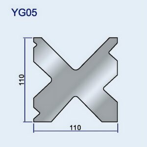
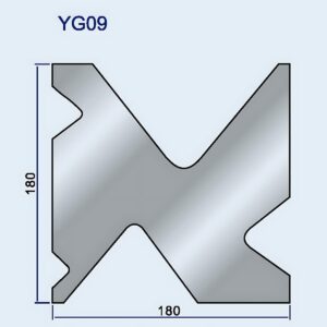
Standard Press Brake Tooling, Press Brake Die
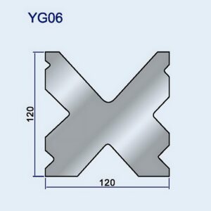
Standard Press Brake Tooling, Press Brake Die
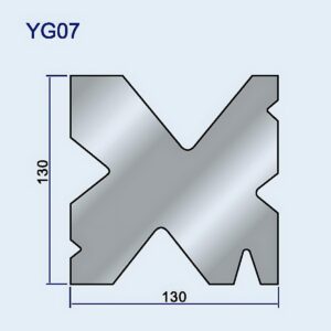
Standard Press Brake Tooling, Press Brake Die
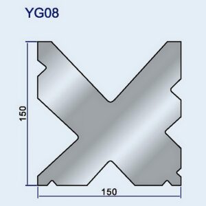
Standard Press Brake Tooling, Press Brake Die
Standard Press Brake Tooling, Press Brake Die
Standard Press Brake Tooling, Press Brake Die
Standard Press Brake Tooling, Press Brake Die
Standard Press Brake Tooling, Press Brake Die
Standard Press Brake Tooling, Press Brake Die
Walk past the scrap bin in almost any mid-sized fabrication shop and you’ll find the same casualties: cracked 304 stainless and over-bent aluminum parts. Operators tend to blame a bad batch of material or a drifting backgauge. In reality, the true offender is already mounted in the press brake bed—masquerading as an innocent block of hardened D2 tool steel.
We treat standard V-dies like interchangeable sockets in a toolbox. If the angle matches the drawing, we clamp it in place and hit the pedal.
But a press brake die is not just a shape-matching accessory. It functions more like a high-pressure control valve.
If you’re selecting from a rack of generic tooling without verifying ratings, geometry, and compatibility, you’re gambling with both safety and accuracy. Modern Standard Press Brake Tooling is engineered around strict tonnage and geometry limits—those limits must guide every setup decision.
Watch a new operator set up for a 90-degree bend in 10-gauge stainless. The required 1/2-inch V-die is tied up on another machine, so he pulls a 3/8-inch V-die from the rack instead. Both dies are machined to the same 88-degree angle. He assumes the narrower die will simply produce a slightly tighter inside radius—maybe leave a minor tooling mark.
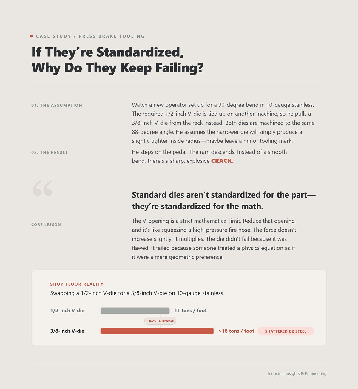
He steps on the pedal. The ram descends. Instead of a smooth bend, there’s a sharp, explosive CRACK.
He’s just learned a hard lesson: standard dies aren’t standardized for the part—they’re standardized for the math. The V-opening is a strict mathematical limit. Reduce that opening and it’s like squeezing a high-pressure fire hose. The force doesn’t increase slightly; it multiplies. The die didn’t fail because it was flawed. It failed because someone treated a physics equation as if it were a mere geometric preference.
Shop Floor Reality: Swap a 1/2-inch V-die for a 3/8-inch V-die on 10-gauge stainless just because the angles match, and you’ll drive required tonnage from 11 tons per foot to more than 18. At that point, don’t be surprised if you’re picking shards of shattered D2 tool steel out of your safety glasses.
Examine a failed part closely, and the metal will tell you exactly how it met its end. The first failure is the most obvious: cracking along the outside of the bend. This occurs when the punch drives harder materials—like HRC 50+ steel—into a V-opening that’s too narrow to allow for the material’s natural elongation. The second is the tonnage overload we just covered: the machine hits its limit, the ram stalls, or the tooling fractures under concentrated stress.
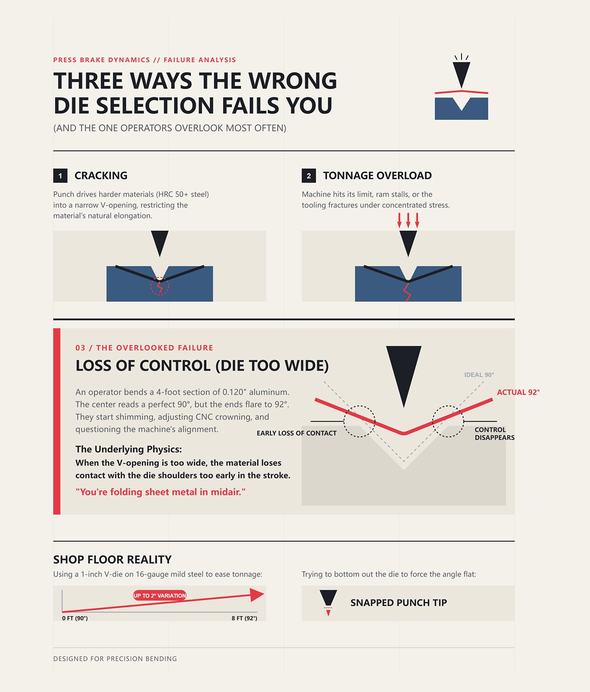
But there’s a third failure mode—and it’s the one that quietly plagues quality control.
It happens when the die is only slightly too wide. An operator bends a 4-foot section of 0.120″ aluminum. The center reads a perfect 90 degrees, but the ends flare to 92. They start shimming the die. They adjust the CNC crowning. They question the machine’s alignment, convinced the bed must be warped. What they’re missing is the underlying physics: when the V-opening is too wide, the material loses contact with the die shoulders too early in the stroke.
Control over the inside radius disappears. The metal begins to drift. You’re no longer precision bending—you’re folding sheet metal in midair and hoping it cooperates.
Shop Floor Reality: Use a 1-inch V-die on 16-gauge mild steel to ease tonnage, and your bend angle can vary by as much as 2 degrees across an 8-foot length. Try to bottom out the die to force the angle flat, and you’ll likely snap the punch tip.
Pull a rejected bracket from the scrap bin and check the inside corner with a set of radius gauges. Most operators assume the punch tip determines that inside radius. It doesn’t. In air bending, the inside radius is primarily dictated by the V-opening width—typically about 16% of the V-width for mild steel. If the print specifies a 0.062″ inside radius and you use a 1/2-inch V-die, the actual radius will land closer to 0.080″.
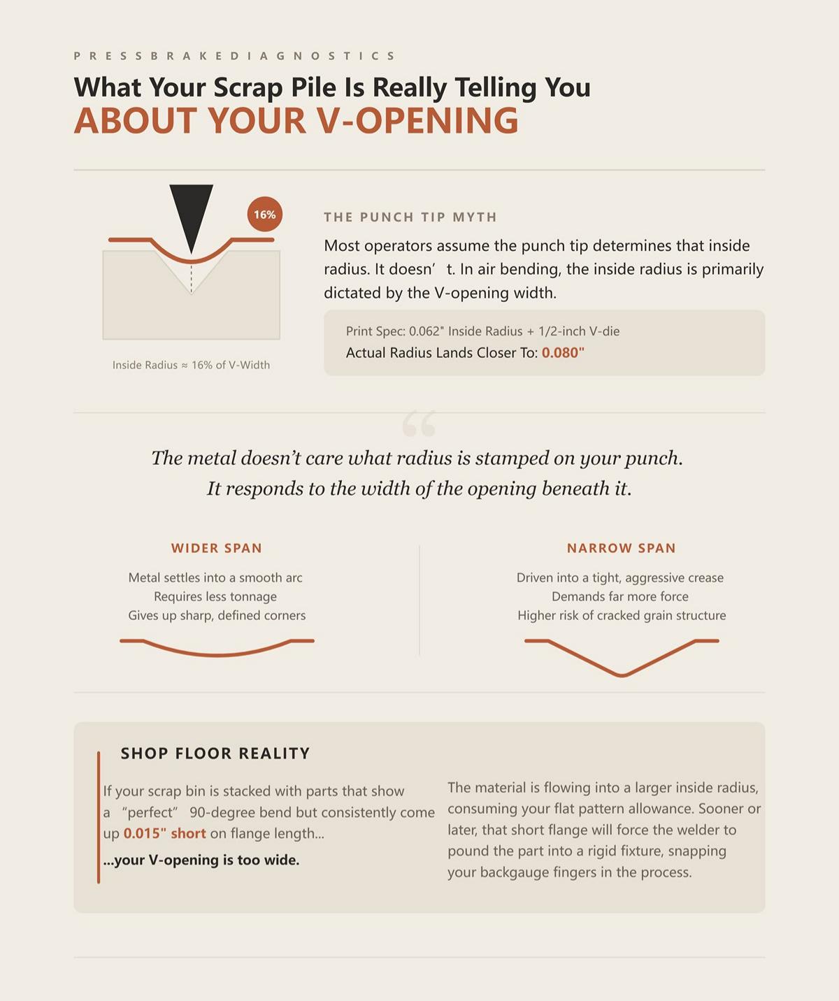
The metal doesn’t care what radius is stamped on your punch. It responds to the width of the opening beneath it.
Think of the V-opening like a suspension bridge: the wider the span between the shoulders, the more the material naturally sags at the center.
Widen the span, and the metal settles into a smooth arc—requiring less tonnage but giving up sharp, defined corners. Narrow it, and the material is driven into a tight, aggressive crease that demands far more force. Every rejected part in the scrap bin—every flange that misses tolerance, every cracked grain structure—tells the same story: someone guessed at the span instead of calculating it. If guesswork keeps filling the bin, why do operators convince themselves they’re doing the math?
Shop Floor Reality: If your scrap bin is stacked with parts that show a “perfect” 90-degree bend but consistently come up fifteen thousandths short on flange length, your V-opening is too wide. The material is flowing into a larger inside radius, consuming your flat pattern allowance—and sooner or later, that short flange will force the welder to pound the part into a rigid fixture, snapping your backgauge fingers in the process.
Ask a first-year apprentice how to choose a die for 16-gauge (0.060″) cold-rolled steel, and they’ll confidently quote the golden rule: multiply the material thickness by eight. They pull a 1/2-inch V-die, step on the pedal, and the press brake hums along at a comfortable 0.8 tons per inch. Why does this simple calculation work so consistently?
Because it balances the load. At eight times material thickness, the inside radius of air-bent mild steel naturally forms at about 16% of the V-opening width. With standard 60,000 PSI tensile steel, that geometry keeps the required force squarely within the optimal range of a typical press brake. How does it relieve that pressure without damaging the metal?
It acts like a high-pressure relief valve.
At the 8× setting, the metal has just enough space to yield and elongate without tearing the outer grain structure, while the die shoulders stay close enough to preserve mechanical advantage. The rule endures because it provides a mathematically sound baseline for the most common shop material. But what happens when the material pushes back?
(When selecting dies for different machine interfaces—whether European style, American standard, or precision-ground systems—verify compatibility before relying on the 8× rule. Systems such as Euro Press Brake Tooling or precision-ground segmented dies may share angles but differ in load capacity and clamping geometry.)
Now watch that same apprentice attempt to bend 1/2-inch A36 plate. He multiplies by eight, wrestles a 4-inch V-die onto the bed, and assumes he’s in the clear. Is he?
Not even close.
As material thickness increases, the tonnage required to form it doesn’t rise in a straight line—it increases exponentially. In fact, it squares. Forcing thick plate into an 8× V-opening generates dramatically more resistance than bending thin sheet. What once served as a safe guideline for light-gauge material now concentrates enormous, localized force directly at the die’s root.
For thicker stock—generally anything over 3/8 inch—you typically need a 10× or even 12× V-opening to distribute that force across a broader shoulder span. High-strength materials such as 304 stainless steel require the same wider opening, regardless of thickness, because their elevated tensile strength resists deformation. Treat the 8× rule as a universal law instead of what it really is—a starting point for mild steel—and you end up blindly overloading your tooling.
So if increasing the V-opening reduces tonnage and protects the die, why not simply use oversized dies for every thick part?
You widen the V-die to 12× to protect your tooling, but the print calls for a 1-inch flange on that 1/2-inch plate. You align the cut edge against the backgauge. The punch descends. Suddenly, the edge of the heavy plate slides off the die shoulder and crashes into the V-opening. How did a decision that reduced tonnage end up destroying the part?
A press brake die, however, is not a simple profile that matches the punch.
It depends on continuous, balanced support across both die shoulders until the bend reaches its final angle. This is the essence of the minimum flange dilemma. As a rule of thumb, the minimum flange length should be at least 70% of the V-opening width.
When you open the die too wide in an effort to lower tonnage on thick plate, the material loses its structural bridge. The part snaps upward, the bend line distorts, and control of the inside radius disappears. You’re trapped by physics: the press brake’s tonnage capacity pushes you toward a wider die, while the part’s short flange demands a narrower one. This is a hard boundary—there’s no negotiating with it, and guesswork will only lead to broken tooling or scrap.
Shop Floor Reality: The Rule of 8 performs well with 16-gauge mild steel at roughly 0.8 tons per inch. But force 1/2-inch A36 plate into a 4-inch V-opening, and that concentrated load can split the die block straight through the root before the bend even reaches 90 degrees.
Watch a rookie attempt to bend 1/4-inch 5052 aluminum. He sees a print specifying a tight 0.062-inch inside radius, grabs a punch with a matching 0.062-inch tip, and sets it up in a standard 2-inch V-die. He steps on the pedal, checks the part, and then stares at a broad 0.312-inch radius sweeping across the bend. The metal completely disregarded the punch geometry.
In true air bending, the punch tip does not create the inside radius—the die opening does. As the punch drives the material downward, the sheet spans the open space between the die shoulders. As it yields, it forms a natural radius mathematically tied to 15.6% of that V-opening. Use a 2-inch V-die, and your inside radius will land around 0.312 inches—whether your punch tip is razor-sharp or blunt as a hammer.
He just learned, the hard way, that standard dies aren’t standardized to the part—they’re standardized to the math.
If you need a tighter radius, you must reduce the V-opening. But narrowing that gap dramatically cuts your mechanical advantage, demanding a sharp increase in hydraulic force to bend the same material thickness. When an operator stubbornly tries to “force” a sharper corner by driving a narrow punch deep into a wide V-die, the punch over-penetrates the die space. The shoulders bottom out against the material, and the resulting stress can shear the punch clamps clean off the ram.
(For applications requiring non-standard radii or geometry, consider purpose-built Special Press Brake Tooling rather than forcing a standard V-die beyond its design limits.)
The air bending tonnage formula (P = 650 × S² × L / V) is printed on nearly every press brake, yet many operators treat it like a magic trick instead of a mathematical model. They plug in material thickness, bend length, and V-opening, then trust whatever number appears. What they overlook is that the “650” constant assumes mild steel with a tensile strength of 450 MPa. Run that same formula for 1/4-inch 304 stainless—typically above 500 MPa—without adjusting the multiplier, and the machine may suggest a safe 15 tons per foot when the material actually requires closer to 25.
It’s essentially a high-pressure valve.
Open the V-opening and the pressure drops to a safe, manageable level. Narrow it based on a flawed calculation, and the force can spike past the tool’s rated capacity in an instant. I once saw an operator blow apart a hardened four-way die block into three pieces because he applied the standard formula to AR400 wear plate without adjusting for its higher tensile strength. The press delivered 120 tons into tooling rated for 80, and the die detonated with a crack that sounded like a shotgun going off.
Even if your tonnage calculation is spot-on for air bending, switching bending methods changes the underlying physics. In air bending, force is distributed across the two shoulders at the top of the V-die. The punch drives downward, while the reaction forces spread outward at opposing angles. But when an operator decides to bottom-bend or coin the part to eliminate springback, the load doesn’t just increase—it relocates. Coining a 1/4-inch plate can demand as much as 600 tons, a staggering jump from the roughly 165 tons required to air-bend that same material.
A press brake die, however, is not merely a form-matching tool.
When you bottom out, the load no longer rests on the die shoulders. Instead, it concentrates at the microscopic root radius at the base of the V-channel. Standard air-bending dies are relieved at the root to provide clearance for the punch tip. Slamming that unsupported cavity with 600 tons of concentrated coining force turns the punch into a wedge, driving straight down the centerline and splitting the die block in two.
The natural instinct is to reach for a wider V-opening every time. It lowers tonnage, extends tool life, and keeps the load safely distributed across the shoulders. But a wider die also creates a larger “floating” span of unsupported material between the punch and die. The more metal suspended in that gap, the more sensitive your bend becomes to changes in ram speed.
Increasing ram speed reduces friction and slightly lowers tonnage, but it can dramatically amplify springback. In a wide die, that springback spreads across a broader surface area, turning a dependable 90-degree bend into an unpredictable 93-degree problem. You can’t correct it simply by driving the punch deeper—the wider gap has already consumed your flat-pattern allowance.
Shop Floor Reality: When you tighten the V-opening to force a sharper 0.062-inch inside radius in 1/4-inch aluminum, you’re not just refining the bend—you’re driving the tonnage requirement up by 1.5×. That’s exactly how the night shift snapped the tang off a $400 standard punch last week.
Watch a new operator attempt to bend 10-gauge A36 mild steel to a precise 90 degrees. He checks the drawing, walks to the tooling rack, and grabs a die clearly stamped “90°.” He installs the punch, lowers the ram until the sheet is fully seated against the die faces, then releases the pedal. When he removes the part and checks it with a protractor, the needle lands at 92 degrees. His first thought? The machine must be out of calibration.
But a press brake die is not a simple shape template.
If you treat the V-opening like a rigid mold, you’re ignoring the basic physics of sheet metal. Metal doesn’t simply fold—it stretches along the outside radius and compresses along the inside. Controlling that internal stress means selecting a die angle based entirely on your bending method: are you allowing the material to float in the air, or are you driving it hard into the steel?
The moment you release tonnage on a bent part, the compressed inner grains push back against the stretched outer grains, causing the material to spring open. This is springback. For 10-gauge A36 steel air-bent to a true 90 degrees under load, the part will typically relax by about 1.5 to 2 degrees as soon as the punch retracts.
To end up with a finished 90-degree angle, you must drive the material to roughly 88 degrees while it is still under load.
This is where die geometry becomes a hard physical constraint. If your die is cut to exactly 90 degrees, the punch physically cannot push the material to 88 degrees. The sheet will contact the V-die faces at 90 degrees and stop. Try to compensate by forcing the ram deeper to “muscle” the angle tighter, and you immediately transition from bending into coining. Tonnage skyrockets—from a manageable 15 tons per foot to well over 100 tons per foot—blowing past the capacity of standard air-bending tooling and potentially snapping the die shoulder clean off. So how do you create the clearance you need without destroying your tooling?
You create the space needed to overbend. Standard tooling catalogs are filled with 85-degree and 88-degree dies for a reason: they intentionally leave a physical void below the 90-degree mark.
An 88-degree die is the default choice for mild steel up to 1/4 inch thick. It provides two degrees of clearance beyond 90, which neatly compensates for the material’s natural springback. But when you switch to materials with greater elastic memory, those two degrees disappear quickly. An 85-degree die offers five degrees of overbend clearance, allowing the punch to drive the material down to 85 degrees before the sheet ever contacts the die faces.
Think of it as a high-pressure relief valve.
Those extra degrees of open space at the bottom of the V-channel let the punch control the final angle through penetration depth, while keeping the tonnage safely distributed across the die shoulders. When an operator insists that an 85-degree die is “wrong” for a 90-degree print, he is overlooking the fundamental purpose of the tool.
He has just discovered—often the hard way—that standard dies are not standardized to the part; they are standardized to the math. But what happens when the material’s memory exceeds even that five-degree safety margin?
As thickness and tensile strength increase, the familiar rules of die geometry begin to unravel. Take 1/4-inch 304 stainless steel as an example. Its springback is significant, often rebounding 3 to 5 degrees. According to the standard “Rule of 8,” the V-opening should be eight times the material thickness—meaning a 2-inch V-die in this case.
When chasing tighter tolerances on hard materials, operators often try to outsmart springback by reducing the V-ratio to six times the thickness. The assumption is that a narrower opening will pinch the radius tighter and force the metal to hold its angle. In reality, dropping below an 8:1 die-to-thickness ratio on hard materials sends tonnage requirements skyrocketing. The force surge causes immediate work-hardening in the confined channel, and the extreme pressure can shear the punch tang straight out of the ram clamp.
To safely bend plate thicker than 6 mm, you must actually increase the V-opening to 10 times the material thickness to keep tonnage within safe operating limits. However, a wider opening produces a larger inside radius, which naturally leads to even greater springback. To compensate for this amplified springback in a wide die, you have to abandon standard 85-degree tooling altogether and switch to a 78-degree—or even a 30-degree acute—die simply to create enough angular clearance to overbend to a true 90-degree corner.
Everything discussed so far applies to air bending, where the material floats within the V-die opening. Bottom bending completely reverses the mathematical relationship between the tooling and the part. In bottoming, the punch deliberately drives the sheet metal firmly against the die faces to set the bend angle and eliminate springback.
Because the material is being forced tightly against the die faces, the die angle must match the intended bend angle. If you need a 90-degree bend, you must use a 90-degree bottoming die.
This is where tooling gets destroyed. An operator decides to bottom-bend a difficult material but leaves a standard 85-degree air-bending die in the press. Now a 90-degree punch is being driven into an 85-degree cavity—with a sheet of steel trapped between them. The clearance that normally protects the tooling during air bending turns into a confinement zone. The punch behaves like a splitting wedge, forcing the trapped material outward against the die faces with no room to relieve the stress.
Shop Floor Reality: Attempt to bottom-bend 12-gauge 304 stainless in an 85-degree air-bending die to overcome 3 degrees of springback, and you will immediately exceed the 12-ton-per-foot rating of standard tooling—cracking the die shoulder clean off.
Picture two blocks of hardened steel resting on a workbench.
They appear identical. Both are stamped “85°” on the side. Yet one is a precision instrument, and the other is a failure waiting to happen. We tend to treat steel as if it were permanent—assuming a block of metal will perform tomorrow exactly as it did yesterday. It won’t.
The V-opening functions like a high-pressure valve: open it too wide and you sacrifice precision along with pressure; choke it down without running the exact calculations and the entire system can fail violently. As tooling inevitably wears, operators often try to “replace the valve” using nothing more than visual memory and a catalog number. What they overlook is this: standard dies are standardized around the math—not around your specific part.
So how do you replace that valve when the numbers have worn away?
Operators love to match the stamp and move on. They see an 85-degree angle and a 1-inch V-opening and assume geometry is the only variable that matters. The tonnage rating barely gets a glance.
Every die carries a clearly defined maximum load limit determined by its internal metallurgy and depth of hardening. A standard 1-inch V-die might be rated for 15 tons per foot, while a heavy-duty version with the exact same visual profile is rated for 25 tons. If you order a replacement based solely on the stamped angle, you are operating blind to the tool’s actual structural capacity.
I have watched someone install a standard-duty 12-ton-per-foot replacement die into a setup intended for 10-gauge A36 steel pulling 14 tons per foot. The visual match means nothing to the physics inside the press. The die cracks straight through the root, sending fragments skidding across the shop floor.
Why would a die that looks identical suddenly fracture under what seem like normal working conditions?
Tooling failure doesn’t just come from ordering mistakes. It also comes from gradual, nearly invisible wear.
The die’s shoulder radius is the exact point where sheet metal drags during the bend. After thousands of parts slide across that surface, the radius begins to flatten. That subtle flattening fundamentally alters the mathematical boundary of your V-opening. As the shoulder spreads, surface contact increases—and with it, drag friction multiplies.
As friction rises, the punch must apply more force to drive the material into the channel. You are no longer simply bending the part—you are battling the tool itself. With every stroke, your true tonnage requirement creeps higher, quietly consuming the safety margin you assumed was there.
Shop Floor Reality: Let the shoulder radius on a 1-inch V-die wear down by just 0.015 inches, and drag friction climbs enough to spike your bending force by 10 percent—turning what should be a safe 15-ton bend into a tooling-shattering overload on your next high-tensile job.
To replace the worn die, purchasing orders a lower-cost substitute from a different manufacturer and installs it right beside your remaining original.
Both are labeled as a 1-inch V-opening. But the new manufacturer machines the V-center 0.005 inches off the original brand’s centerline. The moment you combine these dies in a single setup, you introduce a tolerance stack. The punch contacts the material over the new die a split second before it touches the old one.
That timing difference generates a severe side thrust. The lateral load rips the punch tang straight out of the ram clamp, destroying the upper tool—all because you tried to save fifty dollars on the lower die.
Is there a tooling system that eliminates this alignment drift altogether?
Multi-V dies—those large blocks machined with 2V, 3V, or even 4V grooves—can look like the ultimate answer to alignment issues.
Because all grooves are cut into a single block of steel, the geometry is locked in, delivering perfectly parallel bends across positions. But that precision comes at a cost. Multi-V setups require perfectly matched upper Z-style punches to clear the bulk of the block. If you mix brands here, alignment drift doesn’t just undermine repeatability—it can drive the upper punch straight into the unused V-shoulders. Single-V dies offer the flexibility to avoid these collisions, but they demand strict, math-driven alignment every time you set up.
And remember, the standard formulas have hard limits. For material thicker than 1/2 inch, the traditional Rule of 8 breaks down completely. You must increase the die opening to at least 10 times the material thickness to prevent excessive pressure—shattering the assumption that V-scaling is universal. You cannot simply drop a larger multi-V block onto the bed and expect the standard rules to protect you.
Shop Floor Reality: Treat a multi-V block like a universal shortcut for bending 5/8-inch plate without expanding to a strict 10× ratio, and the trapped material can launch the entire block off the bed—once again proving that standard dies are standardized for the math, not for your specific part.
Structural integrity is not something you can judge by eye. When an operator selects a tool simply because it appears to match the profile on the drawing, he is creating a serious hazard. Standard dies are not standardized for the part—they are standardized for the math.
The math is your only safeguard against catastrophic failure. This is not a theoretical exercise reserved for engineering; it is a disciplined sequence of calculations that must be completed at the control pedestal before the foot pedal is ever pressed. We are going to establish clear mathematical boundaries for your bend, starting with the raw material and ending at the physical limits of your tooling.
Shop Floor Reality: Run this four-step calculation every single time. Assuming that a 2-inch V-opening can handle 1/4-inch Grade 50 steel at 18 tons per foot is exactly how you end up with a cracked die bed and a week of unplanned downtime.
Your baseline always begins with the Rule of 8: the V-opening should equal eight times the material thickness. However, this guideline was developed for approximately 60,000 PSI tensile-strength cold-rolled steel. When you move to 304 stainless or high-strength low-alloy plate, the multiplier must immediately increase to 10x or even 12x to account for the material’s greater resistance to plastic deformation. Ignore the material type and try forcing 1/4-inch AR400 plate into a standard 2-inch V-opening, and the material will not yield in a controlled, predictable manner.
This is where the math exposes inexperience.
After calculating the appropriate V-opening based on thickness and tensile strength, immediately verify your minimum flange length. The flange must measure at least 70 percent of the V-opening to bridge the die gap safely during the stroke. Attempting to bend a 0.5-inch flange on 10-gauge steel over a 1.25-inch V-opening will cause the short leg to slip off the shoulder mid-stroke. The raw edge can wedge between the punch and the die wall, potentially chipping the hardened punch tip and creating a dangerous situation.
Shop Floor Reality: Never chase an unrealistically tight inside radius at the expense of minimum flange requirements. If the math shows the flange is too short for the required V-opening, send the drawing back to engineering before you sacrifice a $400 punch.
Once you’ve identified a baseline V-opening that satisfies your flange constraints, the next step is to calculate the precise force required to drive the material into the die. Think of it like a high‑pressure valve: open it too wide and you sacrifice accuracy; restrict it too much without running the numbers, and the entire system can fail catastrophically.
Every time you reduce the V-opening to achieve a tighter inside radius, the required tonnage rises dramatically. Bending 1/4-inch A36 steel over a 2-inch V-opening requires approximately 15.3 tons per foot. If an operator tightens that “valve” to a 1.5-inch V-opening to force a sharper radius, the requirement jumps to more than 22 tons per foot. On a 10-foot press brake rated at 150 tons, a full-length bend at this setting would demand 220 tons—well beyond the machine’s capacity.
The machine will attempt to deliver that load. The hydraulic cylinders will deadhead against the resistance of the undersized die, blowing main cylinder seals and potentially cracking the lower die bed straight through its center web.
Shop Floor Reality: The tonnage chart mounted on your machine is not a guideline—it is a hard limit. If your calculated V-opening requires more tonnage per foot than your ram can supply, you must increase the V-opening and accept a larger inside radius.
You may have the correct V-opening and sufficient ram capacity—but a press brake die is not a simple angle template. If you are air bending—which should account for roughly 90 percent of your work—the die angle must be significantly more acute than the finished part angle to allow for proper overbending.
Metal has elastic memory. Standard mild steel typically springs back 1 to 2 degrees, meaning you’ll need an 85-degree die to air bend a true 90-degree angle. High-strength materials such as AR400 can spring back as much as 15 degrees, requiring a 70-degree—or even 60-degree—die. Inexperienced operators overlook this elastic recovery. They see a 90-degree specification on the print, select a 90-degree die, and then scramble when the finished part measures 93 degrees.
To compensate, they abandon air bending and switch to bottoming. They drive the punch deep into the 90-degree V-die at maximum tonnage, attempting to force the springback out of the material. Bottoming 1/4-inch plate in a die intended for air bending can multiply the required tonnage by five—often enough to split the die block in two and send the fractured pieces flying across the shop floor.
Shop Floor Reality: For mild steel, always choose a die angle at least 5 degrees tighter than your target bend. Trying to eliminate springback by brute-force bottoming will destroy your tooling—every time.
The machine has sufficient capacity, the V-opening is correct, and the bend angle accounts for springback. The final constraint is purely structural: the load limit of the specific steel die block sitting on your press brake.
Every die comes with a maximum load rating, typically stamped on the end of the tool or listed in the manufacturer’s catalog as a strict tons-per-foot value. This limit is determined by the V-channel depth, shoulder width, and the die’s internal metallurgy. For example, a standard 30-degree acute die with a 1-inch opening may be rated for 12 tons per foot, while a heavy-duty 85-degree die with the same opening might safely handle 20 tons per foot.
You must compare the required tonnage calculated in Step 2 with the load rating of the die selected in Step 3. If your 10-gauge stainless steel part requires 14 tons per foot and you place it in a 30-degree acute die rated for 12 tons per foot, the machine will not hesitate. The press brake will calmly deliver 14 tons into a tool engineered to withstand only 12. The die will likely fracture at the base of the V on the very first hit—ruining your setup and potentially costing you your fingers.
Shop Floor Reality: The die’s load rating is the absolute limit in any press brake setup. If your bend requires 18 tons per foot and the die is rated for 15, you don’t “try it and see”—you select a larger, properly rated die.
| Step | Title | Key Actions | Technical Details | Risks if Ignored | Shop Floor Reality |
|---|---|---|---|---|---|
| Step 1 | Start with Material Thickness, Type, and Minimum Flange Length | Determine V-opening using Rule of 8 baseline; adjust multiplier based on material tensile strength; verify minimum flange length | Rule of 8 (V = 8× thickness) applies to ~60,000 PSI cold-rolled steel; use 10×–12× for 304 stainless or HSLA; flange must be ≥70% of V-opening | Material won’t deform predictably; short flange can slip into die gap; tooling damage (chipped punch tip); unsafe conditions | Never sacrifice minimum flange requirements for a tight inside radius; if flange is too short, return drawing to engineering |
| Step 2 | Estimate the V-Opening and Confirm Against Machine Tonnage Charts | Calculate required tonnage per foot; compare against machine capacity; adjust V-opening if necessary | Smaller V-opening dramatically increases tonnage; example: 1/4″ A36 over 2″ V ≈15.3 tons/ft; over 1.5″ V >22 tons/ft; 10-ft bend could exceed 150-ton machine rating | Overloading press brake; blown hydraulic seals; cracked die bed; catastrophic machine failure | Tonnage chart is a hard limit; if required tonnage exceeds capacity, increase V-opening and accept larger radius |
| Step 3 | Validate Die Angle Against Bending Method and Springback Expectations | Select die angle suitable for air bending; account for material springback; avoid unnecessary bottoming | Mild steel springs back 1–2° (use ~85° die for 90° bend); AR400 may spring back up to 15° (require 70°–60° die); bottoming can multiply tonnage by five | Incorrect bend angles; excessive tonnage; cracked die blocks; flying debris; tooling destruction | For mild steel, choose die angle at least 5° tighter than target; do not attempt to eliminate springback by brute-force bottoming |
| Step 4 | Verify the Die’s Load Rating Before Running the First Part | Check die’s tons-per-foot rating; compare with calculated tonnage; select properly rated die | Load rating based on V-depth, shoulder width, metallurgy; example: 1″ 30° die rated 12 tons/ft vs. heavy-duty 85° die rated 20 tons/ft | Die fracture at V-base; damaged tooling; severe injury risk | Die load rating is absolute; never exceed rated tons per foot—select a larger die if required |
Every failed bend, cracked die, and shattered punch in your scrap history traces back to one decision: ignoring the math.
Whether you are evaluating Press Brake Toolings for a new machine, replacing worn dies, or solving a springback problem on high‑tensile material, the selection process must start with tensile strength, thickness, flange length, tonnage, and die load rating—not with what “looks right” on the rack.
If you’re unsure whether your current tooling is properly rated for your application—or you’re facing repeat die failures—Contact us for a technical review of your setup. You can also download detailed specifications and load charts directly from our product Brochures to verify compatibility before your next run.
Because in press brake bending, the math always wins.
And steel never forgives guesswork.
 العربية
 বাংলা
বাংলা
 Български
 Čeština
 Dansk
Dansk
 Nederlands
 Suomi
Suomi
 Français
 Deutsch
 Ελληνικά
 עִבְרִית
 हिन्दी
 Magyar
 Bahasa Indonesia
 Italiano
 日本語
日本語
 Қазақ тілі
 한국어
한국어
 Bahasa Melayu
 Norsk bokmål
 فارسی
فارسی
 Polski
 Português
 Română
 Русский
 Српски језик
 Slovenčina
 Español de México
 Español
 Kiswahili
 Svenska
 Tagalog
 தமிழ்
தமிழ்
 ไทย
ไทย
 Türkçe
 Українська
 اردو
اردو
 Tiếng Việt
 简体中文
简体中文
 香港中文
香港中文
 繁體中文
繁體中文
