Showing 1–9 of 24 results
Press Brake Die, Wila Press Brake Tooling
Press Brake Die, Wila Press Brake Tooling
Press Brake Die, Wila Press Brake Tooling
Press Brake Die, Wila Press Brake Tooling
Press Brake Die, Wila Press Brake Tooling
Press Brake Die, Wila Press Brake Tooling
Press Brake Die, Wila Press Brake Tooling
Press Brake Die, Wila Press Brake Tooling
Press Brake Die, Wila Press Brake Tooling
A press brake is essentially a high-pressure hydraulic vise. The tooling you load into it serves as a mechanical fuse—positioned between the raw force of the ram and the resistance of the sheet metal.
When everything is properly aligned, the metal forms as intended. When your calculations are off, that “fuse” doesn’t simply fail—it detonates.
Yet every day, operators flip through glossy tooling catalogs, see the word “compatible,” and place the order. They treat a 200-ton press brake like a desktop printer that can run on any off-brand ink cartridge.
If you are evaluating different brands of Press Brake Toolings, this is the moment to slow down—because compatibility is not a marketing label. It’s a structural calculation.
I once watched a night-shift operator install a “Wila-compatible” American tang punch into a New Standard hydraulic clamp. He stepped on the pedal. When the 150-ton ram descended, the die failed to seat—kicking sideways, shearing the clamp off the beam, and blasting fragments into the safety glass. That single word in a catalog ended up costing the shop $14,000 in repairs and three weeks of downtime. Assuming a brand name guarantees universal fit ignores the physical realities of the machine. A hydraulic cylinder does not negotiate.
Shop Floor Reality: If you don’t confirm the exact tang profile before hitting the pedal, you’re not saving time—you’re assembling an explosive device.
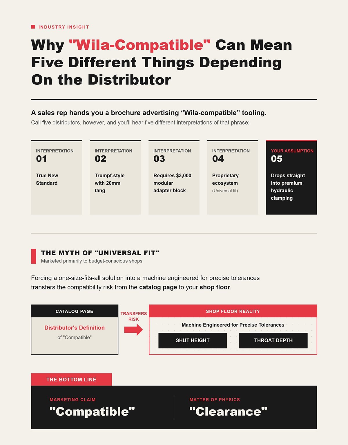
A sales rep hands you a brochure advertising “Wila-compatible” tooling. You assume that means it will drop straight into your premium hydraulic clamping system. Call five distributors, however, and you’ll hear five different interpretations of that phrase. One defines it as true New Standard. Another means Trumpf-style with a 20mm tang. A third requires a $3,000 modular adapter block just to secure the tool in your ram.
In practice, compatibility depends on the exact mounting logic—whether you are working with true New Standard profiles, legacy European systems, or machine-specific formats such as Trumpf Press Brake Tooling or Euro Press Brake Tooling. Meanwhile, the manufacturer may insist their proprietary ecosystem delivers universal fit across any press brake platform.
In reality, “universal fit” is a myth marketed to budget-conscious shops.
When you force a one-size-fits-all solution into a machine engineered for precise tolerances, you’re transferring the compatibility risk from the catalog page to your shop floor. You’re betting that the distributor’s definition of “compatible” aligns perfectly with your brake’s shut height and throat depth.
Shop Floor Reality: “Compatible” is a marketing claim. “Clearance” is a matter of physics.
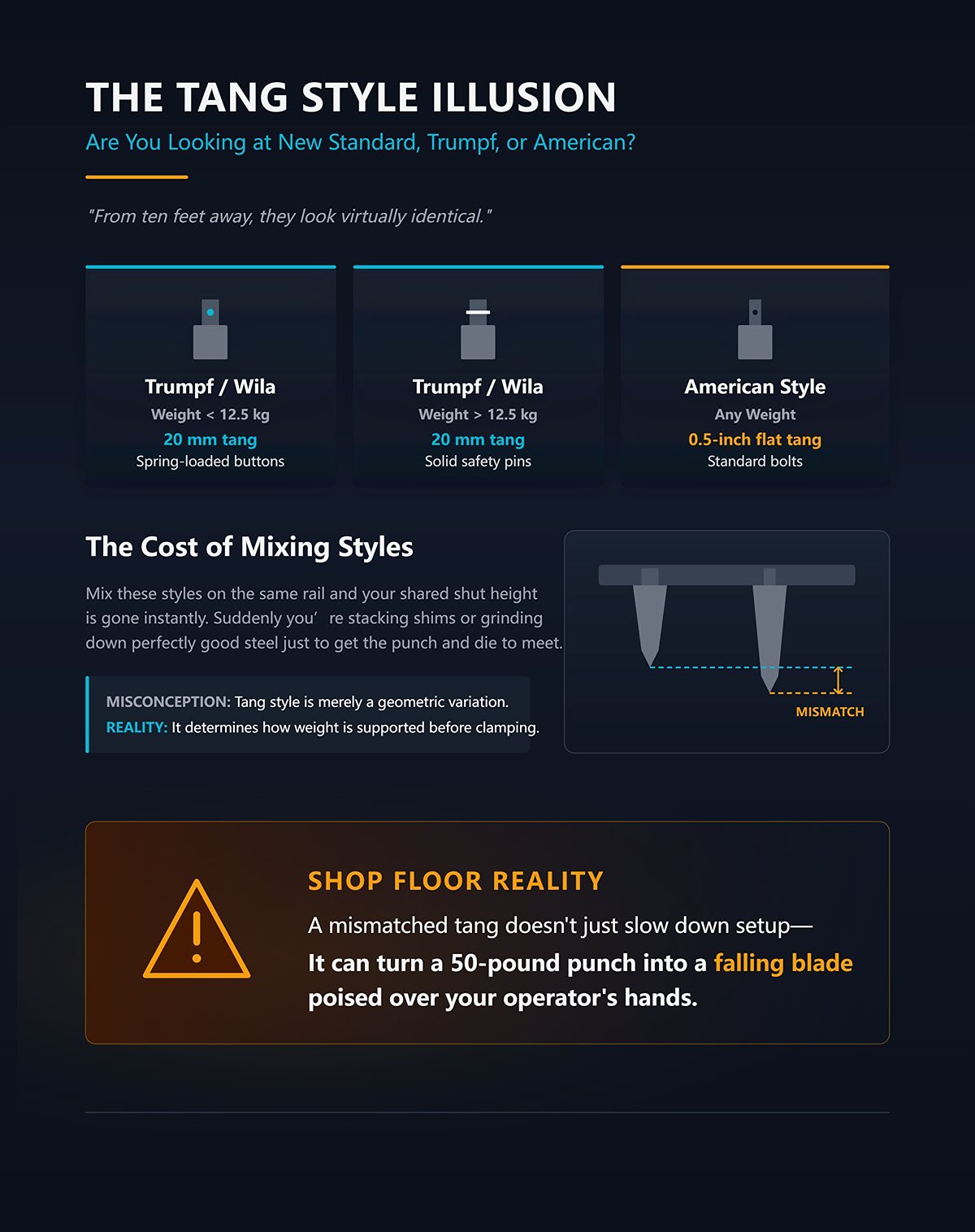
Take a pair of calipers and measure a Trumpf-style Wila punch. You’ll find a 20 mm tang fitted with spring-loaded buttons, engineered to secure tools weighing under 12.5 kg. Now pick up a heavier punch from the same catalog family and those spring buttons disappear—replaced by solid safety pins. Measure an American-style tool and you’ll see a 0.5-inch flat tang fastened with standard bolts.
From ten feet away, they look virtually identical.
Whether you’re selecting New Standard, American, or dedicated systems such as Amada Press Brake Tooling, the tang geometry determines how the tool seats and how the load path transfers into the ram.
Mix these styles on the same rail and your shared shut height is gone instantly. Suddenly you’re stacking shims or grinding down perfectly good steel just to get the punch and die to meet. The misconception is that tang style is merely a geometric variation. In reality, the tang design determines how the tool’s weight is supported before the clamp even locks in.
Shop Floor Reality: A mismatched tang doesn’t just slow down setup—it can turn a 50-pound punch into a falling blade poised over your operator’s hands.
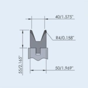
You find a die with a 12 mm V-opening that matches your material thickness. The tang fits your clamp. It feels like you’re ready to bend. But that V-opening spec tells you nothing about the tool’s structural limits under your machine’s full tonnage. The catalog may list a maximum load of 30 tons per foot for that specific V-opening.
If your machine’s throat depth forces you to bend off-center, or if the die’s overall height exceeds your slide stroke by just 5 millimeters, you may not even be able to install the tool without bottoming out the ram. In that scenario, you could be applying 50 tons per foot to a die rated for 30—all because you focused on the V-opening instead of calculating the true working height.
For tighter radii applications, dedicated profiles such as Radius Press Brake Tooling may reduce surface damage—but only if their tonnage ratings align with your forming method.
Shop Floor Reality: Getting past the tang-style illusion may let the tool fit the machine—but ignore tonnage calculations and clearance limits, and you’ll still end up snapping the die in two.
Wila’s catalog promotes its “Universal Press Brake concept” as a way to run premium tooling on virtually any press brake through the use of adapter holders. It sounds straightforward: bolt an adapter block onto your legacy machine and you’re suddenly operating with top-tier New Standard punches. But the moment you introduce an adapter, you interrupt the direct transfer of force into the ram. Instead of a clean load path, the force now travels through an intermediary.
That’s why clamping and load distribution systems—such as engineered Press Brake Clamping and properly matched Press Brake Die Holder configurations—must be evaluated as part of the total force path, not as accessories.
A setup rated at 90 tons per foot can drop to an unpredictable fraction of that capacity because the load is constrained by the adapter’s mounting bolts. True compatibility is never about the brand—it’s about the integrity of the load path.
Shop Floor Reality: Choosing tooling based on the logo instead of the mounting logic is like installing a diesel engine in a gasoline car simply because you trust the brand.
Place a Wila New Standard holder next to a Wila Trumpf-style holder. Both carry the same premium branding and promise exceptional precision. But mechanically, they operate on entirely different principles. The New Standard system uses a single, continuous clamping mechanism that draws the tool upward, seating it firmly against load-bearing shoulders. Force is transmitted directly through those shoulders, enabling capacities of 90 tons per foot (300 tons per meter, per the catalog). The Trumpf-style system, by contrast, depends on a 20 mm tang and a distinct load path that seats differently within the beam.
Attempt to force a Trumpf-style punch into a New Standard clamp simply because the catalog says “Wila,” and the hydraulic pins will fail to engage the safety groove. The tool will sit slightly out of alignment, bearing on the tang instead of the shoulders. When the ram descends, the full 90 tons per foot bypasses the engineered load path and transfers directly into the clamping pins—shearing them almost instantly. The brand identifies the manufacturer; the style defines the mechanical language of the machine. But even if the style matches, does that guarantee the holder will mount to your machine safely?
Shop Floor Reality: Choosing tooling based on the logo instead of the mounting logic is like installing a diesel engine in a gasoline car simply because you trust the brand.
| Aspect | Wila New Standard | Wila Trumpf-Style |
|---|---|---|
| Brand | Wila | Wila |
| Core Mechanical Principle | Single, continuous clamping mechanism that draws the tool upward and seats it against load-bearing shoulders | Uses a 20 mm tang with a distinct load path that seats differently within the beam |
| Load Transmission | Force transmitted directly through load-bearing shoulders | Force transmitted through tang-based seating system |
| Capacity | 90 tons per foot (300 tons per meter, per catalog) | Depends on tang-based system design |
| Clamping Behavior | Hydraulic system engages safety groove and secures tool firmly against shoulders | Relies on proper tang engagement within beam structure |
| Result of Incorrect Installation | Trumpf-style punch will not engage safety groove; tool sits misaligned and bears load incorrectly | When forced into New Standard clamp, full 90 tons per foot transfers into clamping pins, shearing them almost instantly |
| Mechanical Compatibility | Requires New Standard-compatible tooling | Requires Trumpf-style-compatible tooling |
| Key Insight | Style defines the mechanical language of the machine—not just the brand | Matching brand does not guarantee mechanical compatibility |
| Shop Floor Reality | Choosing tooling based on logo instead of mounting logic is like installing a diesel engine in a gasoline car simply because you trust the brand | Mechanical compatibility must be verified beyond branding |
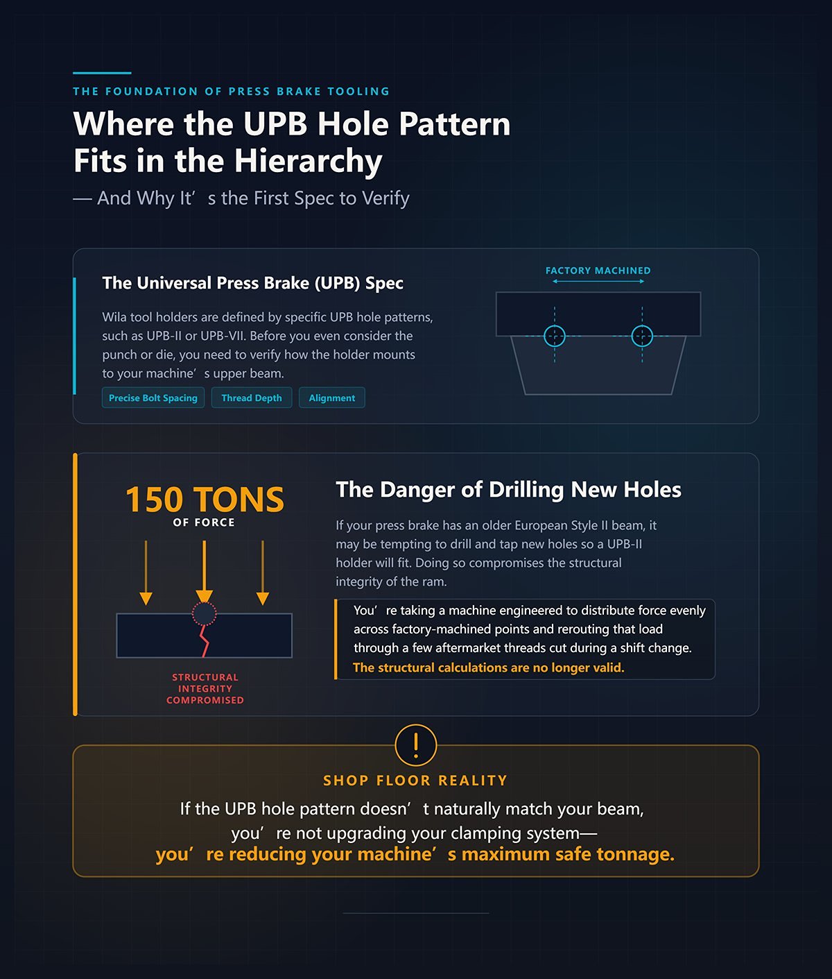
Wila tool holders are defined by specific Universal Press Brake (UPB) hole patterns, such as UPB-II or UPB-VII. Before you even consider the punch or die, you need to verify how the holder mounts to your machine’s upper beam. A UPB-II pattern specifies precise bolt spacing, thread depth, and alignment. If your press brake has an older European Style II beam, it may be tempting to drill and tap new holes so a UPB-II holder will fit.
Doing so compromises the structural integrity of the ram. You’re taking a machine engineered to distribute 150 tons of force evenly across factory-machined mounting points and rerouting that load through a few aftermarket threads cut during a shift change. The holder may appear to sit flush, but the structural calculations behind the machine are no longer valid. The hole pattern is the foundation of your mechanical safety system—undermine it, and the entire setup becomes a liability. Once the holder is correctly mounted, the next question is: what determines the size of the tools you can actually load into it?
Shop Floor Reality: If the UPB hole pattern doesn’t naturally match your beam, you’re not upgrading your clamping system—you’re reducing your machine’s maximum safe tonnage.
On a night shift back in ’08, the crew tried to bottom out a 4-inch-deep part using a tall punch and a standard die block. They confirmed the V-opening and checked the tang style, but they failed to calculate the daylight—the maximum open distance between the upper and lower beams. The machine had 12 inches of daylight. The punch stood 6 inches tall, the die measured 4 inches, and the part required 4 inches of upward clearance to fold. That’s 14 inches of required space inside a 12-inch opening.
When they pressed the pedal, the sheet metal jammed against the ram before the bend was complete. The 200-ton hydraulic system didn’t care that there was no remaining clearance. It kept driving forward, delivering roughly 60 tons per foot into a dead stop. The force split the machine’s side frames clean down the middle.
The machine failed before the metal ever bent.
Daylight clearance is a hard physical constraint, not a flexible guideline. You cannot override the stroke limit of a hydraulic cylinder. Even if the die physically fits within the daylight, how do you ensure it stays secure when the ram retracts?
Shop Floor Reality: Your machine’s daylight sets the absolute ceiling for tooling height. Ignore that calculation, and a routine bend can turn into a catastrophic dead-stop collision.
For lighter tools under 25 pounds, spring-loaded buttons are sufficient to hold the segment in the clamp until the hydraulics fully engage. Move up to a heavier punch from the same product line, however, and those spring buttons are replaced with solid safety pins. A 500 mm segmented punch weighs roughly 40 pounds. If your clamping system is an older manual design—or lacks the internal recess required to accept that solid safety pin—the pin will physically prevent the tang from seating flush against the load-bearing shoulders.
Some operators grind off the safety pin just to make the tool fit. Now you have a 40-pound block of hardened steel suspended by friction alone. When the clamp releases, that punch drops straight down. The safety pin is a mandatory mechanical interlock, not an optional add-on. But even once the tool is properly secured and your daylight calculations check out, how can you be certain the die’s geometry won’t fail under actual bending force?
Shop Floor Reality: Grinding off a safety pin to force compatibility turns a minor tooling mismatch into an immediate—and potentially fatal—drop hazard.
When everything is properly aligned, the metal yields as expected. But achieving that alignment requires looking beyond the catalog’s basic dimensions and understanding the underlying physics of the press brake.
A fabricator in Texas ignored the 30-tons-per-foot limit on a sharp V-die while attempting to coin quarter-inch stainless steel. He had a 300-ton press brake and a 10-foot part, so he assumed he was well within the machine’s capacity. He was right about the machine—but wrong about the math. The die split straight down the gullet with a sound like a shotgun blast and permanently warped the lower beam.
Standard tonnage formulas establish the baseline force required to bend a given thickness of steel. For example, bending 3 mm mild steel over a 24 mm V-opening requires approximately 20.8 tons per meter. An operator sees that number, checks a 150-ton press brake, and assumes there is plenty of capacity. But tooling catalogs rate dies by tonnage per meter (or per foot), not by total machine capacity.
If you concentrate a heavy load on a short 6-inch section of a standard Wila-style die, the machine’s overall tonnage rating becomes irrelevant. You may be driving 100 tons of force into a localized die shoulder designed to withstand only a fraction of that load. A press brake functions like a high-pressure hydraulic vise, with the die serving as the mechanical fuse. Miscalculate the load, and that fuse doesn’t simply fail—it can fracture violently.
Shop Floor Reality: If you fail to compare your forming method’s tons per foot to the die shoulder’s rated capacity, it’s only a matter of time before a tool snaps in half.
Air bending a 10-foot sheet of quarter-inch mild steel typically requires about 165 tons of force. The sheet rests on the die shoulders while the punch descends, and the material forms as it spans the V-opening.
Switch to bottoming—where the punch drives the material fully into the V-die to minimize springback—and that same sheet can demand as much as 600 tons.
That represents nearly a 400 percent increase in load. Tooling catalogs base their standard tonnage charts on air bending because it is the most common—and most forgiving—forming method. As a result, they market what they call a “standard” die. Ask five distributors what that means, and you may hear five different definitions.
If you purchase a die rated for a 165-ton air bend and then use it for a bottoming operation, you immediately compromise its structural integrity. Instead of the force being absorbed primarily by the yielding metal, it transfers directly into the die body.
Shop Floor Reality: Using air-bending tonnage charts to plan a bottoming operation turns your die into an underrated mechanical fuse—one that’s primed to fail.
The standard rule of thumb calls for a V-opening that is eight to ten times the material thickness. A wider die opening lowers the required tonnage, but it also increases the natural inside bend radius and the amount of springback you must account for.
When an operator needs a tighter inside radius on thick stainless steel, the instinct is to switch to a narrower V-opening. But stainless steel already demands roughly 50 percent more tonnage than mild steel just to begin yielding. Force it into a tight die, and your mechanical advantage shrinks while the required pressure surges. Instead of flowing smoothly over the die shoulders, the material starts to drag. At that point, you’re no longer bending—you’re extruding. The intense, localized friction leads to galling, destroys the surface finish, and strips the hardened layer from the die shoulders. The die geometry should determine the achievable radius—not the operator’s brute force.
Shop Floor Reality: Forcing a tight inside radius with a narrow V-opening on high-tensile material will wreck your surface finish and permanently scar your die shoulders.
Modern CNC controls use proprietary algorithms to calculate tonnage automatically, factoring in die opening, material thickness, and tensile strength in real time. On the surface, it seems foolproof.
It’s not. Standard unit pressure charts—such as those specifying 360 kilonewtons per meter for a 45 mm V-opening—assume a continuous, solid die block. In real-world applications, complex parts require segmented tooling to clear flanges and internal features. Once you break the bend line into multiple short die segments, you lose the uninterrupted structural support of a solid block.
The CNC controller assumes the load is evenly distributed across a single, monolithic piece of steel. It cannot account for the physical gaps between your 100 mm and 50 mm segments. Those joints become stress concentrators. Pick up a heavier punch from the same product line and you may notice the spring-loaded retention buttons have been replaced with solid safety pins—a clear sign that the tool’s mass and load characteristics have changed.
If the CNC blindly applies a uniform tonnage calculation to a segmented die line, the individual sections can flex, shift, or even crack along the seams.
Shop Floor Reality: A CNC controller’s tonnage algorithm can’t see the gaps in segmented tooling. The math is only as safe as the operator who verifies the actual load path.
I once had a shop owner try to cut costs by 30 percent, opting for a bargain set of surface-hardened segmented dies from a discount catalog. He was bending half-inch AR400 plate at roughly 50 tons per foot. Within three weeks, the concentrated load didn’t just accelerate wear—it collapsed the die shoulders so severely that the material flowed sideways, seizing the segments in the rail. We ended up driving them out of the press brake with a sledgehammer. A press brake is essentially a high-pressure hydraulic vise, and the die acts as a mechanical fuse. If your calculations are wrong, that fuse doesn’t fail quietly—it detonates.
When everything is aligned correctly, the metal yields.
But when concentrated force meets inferior steel, the die yields instead. Deep hardening and purpose-built segmentation profiles aren’t premium add-ons—they’re structural requirements for heavy forming applications. They determine whether your tooling survives its first production run. Shop Floor Reality: Paying for deep hardening isn’t indulgence; it’s the only way to keep segmented dies from fusing themselves into scrap under extreme loads.
If your production frequently involves tight radii, heavy stainless, or abrasion-resistant plate, reviewing detailed specifications in technical Brochures can clarify hardening depth, material grade, and tonnage ratings before you commit to a purchase.
Shop Floor Reality: Paying for deep hardening isn’t indulgence; it’s the only way to keep segmented dies from fusing themselves into scrap under extreme loads.
Surface treatments such as nitriding or conventional case hardening typically deliver an impressive 55–65 HRC on paper. In a catalog, that sounds virtually indestructible. In reality, that hardness extends only about 0.010 to 0.030 inches below the surface.
Beneath that thin, brittle layer lies comparatively soft, untreated steel.
When heavy-gauge stainless slides across a V-die shoulder, friction combined with downward force generates an intense subsurface shear zone. At 40 tons per foot, that shallow hardened layer flexes against the softer core beneath it and fractures like an eggshell. CNC deep hardening—typically achieved through targeted induction heating—drives 60 HRC hardness to depths of 0.150 inches or more at the working radii. That deeper hardened zone carries the structural load path from the shoulder into the body of the die, preventing the surface from collapsing under pressure.
Call five different distributors, and you will hear five completely different definitions of that term. A catalog may tout an impressive HRC number while conveniently omitting the depth of that hardness—or gloss over the fact that the hardening process itself can introduce internal stresses that cause dimensional drift after quenching.
Shop Floor Reality: Surface hardness ratings are little more than catalog theatrics if the hardened layer isn’t deep enough to withstand the subsurface shear stress generated by your most demanding bends.
A standard 500 mm solid die block spreads forming tonnage evenly across its full length. When you invest in a segmented kit—typically divided into 200 mm, 100 mm, 50 mm sections, plus various ear pieces—you are deliberately introducing vertical fracture lines into what would otherwise be a continuous foundation. Many shops purchase fully segmented sets under the broad promise of “flexible finishing,” assuming they will eventually need the clearance for complex flange geometries.
In reality, those segments usually remain bolted together in a straight line, performing routine air bends.
This is an expensive mistake. Every seam between segments is a potential micro-gap. If the manufacturer failed to precision-grind the mating surfaces after heat treatment, post-quench distortion all but guarantees the sections will not sit perfectly flush. Apply 30 tons per foot across a poorly matched joint, and the high side absorbs a disproportionate share of the load—accelerating wear and stamping a visible witness mark into your parts.
Pick up a heavier punch from the same product line and you may notice the spring buttons have been replaced with solid safety pins. That change is not cosmetic; it’s a clear signal that the tool’s mass and load dynamics demand absolute rigidity, not theoretical flexibility.
Shop Floor Reality: Purchasing segmented dies for “future flexibility” while keeping them assembled as a single block injects unnecessary fracture points into your load path and virtually guarantees uneven tooling wear.
True compatibility starts by reverse-engineering your die selection around your machine’s specific clamping system and your real-world stage bending requirements. Stage bending enables an operator to execute three or four distinct bends in a single handling of the part, progressing from left to right across the bed.
When forming a deep box with return flanges, for example, you need segmented horn punches and window dies that provide precise clearance for the sides that have already been bent.
Clearance is a matter of geometry; staging is a matter of tonnage.
Set up a 100 mm segment for a heavy bottoming operation and a 50 mm segment beside it for a lighter air bend, and the ram still descends in one uniform stroke. The tonnage per foot, however, is now dramatically uneven across the bed. If your press brake’s crowning system cannot isolate and compensate for that localized 60-ton-per-foot spike on the 100 mm segment, the ram will deflect, the bend angle will open up, and the die will absorb the surplus force.
You can’t choose segment lengths based solely on what fits inside the box. You must calculate whether your machine’s hydraulics and crowning system can withstand the asymmetrical load those segments create.
Shop Floor Reality: Segmented stage setups only succeed if your press brake’s crowning system and tonnage capacity can manage the uneven pressure spikes caused by mismatched tooling profiles.
Think of your press brake as a high-pressure hydraulic vise and your tooling as a mechanical fuse. Get the math wrong, and the fuse doesn’t simply fail—it detonates.
We spend hours debating brand names, treating “OEM” and “Aftermarket” like articles of faith instead of engineering decisions. You want to cut costs. I want to keep you from wrecking your ram. To close that gap, we have to strip away the marketing gloss and focus on what actually happens to a block of steel when it’s crushed between a hydraulic cylinder and the lower bed.
Brand loyalty is expensive. Ignorance is ruinous.
The question isn’t OEM versus aftermarket—it’s whether the tooling’s steel grade, hardening depth, tang accuracy, and tonnage rating truly match your machine’s mechanical limits. Reputable manufacturers such as Jeelix provide full-system tooling options across multiple interface standards, allowing shops to match tang style, clamping logic, and load capacity to their specific brake configuration.
Modern Wila hydraulic clamping pins apply approximately 725 psi of pressure to the tool tang. The system is engineered to automatically compensate for minor dimensional variations, ensuring the die seats securely along the intended load path. Because this adaptive clamping works so well, many shops assume they can insert any “Wila-compatible” tool into the holder and expect flawless air bends.
Call five different distributors, though, and you’ll hear five different definitions of what that actually means.
Some aftermarket tools genuinely deliver an impressive ±0.02 mm positioning accuracy. Their catalogs highlight this figure in bold, pushing you toward the premium tier. Before you sign off on that purchase, take a hard look at your machine’s maintenance records. If you’re running a ten-year-old press brake with worn gib ways and ram repeatability of only ±0.05 mm, investing in a die rated at ±0.01 mm is a complete misallocation of capital. The machine’s mechanical play will completely negate the tool’s added precision. It’s like buying a surgical scalpel to split firewood.
Shop Floor Reality: Never pay for a tooling tolerance that exceeds your press brake’s actual ram repeatability.
When everything is properly aligned, the material yields as expected.
But when you’re driving 30 tons per foot into a V-die, fatigue isn’t determined by the logo stamped on the side of the tool. It comes down to the steel’s grain structure and the depth of its heat treatment. Many premium aftermarket manufacturers use the same 42CrMo4 steel specified by OEMs. On paper, the chemical composition is identical.
The real difference emerges during thermal processing. If an aftermarket supplier trims costs by accelerating the induction hardening cycle, the hardened layer may extend only 0.040 inches deep instead of the OEM standard of 0.150 inches. In light-gauge sheet metal applications, you may never notice. In heavy plate work, however, that shallow case hardening can begin to micro-fracture. The die won’t necessarily fail on day one, but after six months of cyclic loading, the working radii will start to flatten. Bend angles will drift. You’ll spend more time compensating with CNC crowning adjustments than actually forming parts.
Shop Floor Reality: Aftermarket steel doesn’t automatically fatigue faster. But if the hardening depth lacks the structural resilience to handle your tonnage peaks, you’ll end up paying for that tool twice—once at purchase, and again in lost setup time.
A warranty is just a piece of paper—until a tool explodes mid-production.
I once saw a shop try to save a thousand dollars by equipping their new 250-ton press brake with off-brand segmented dies. The tang tolerances were loose, but the hydraulic clamping system forced everything into position. During a run of 1/4-inch titanium—at roughly 20 tons per foot—the die shifted under an uneven load. As the ram descended, the misaligned punch clipped the edge of the V-die shoulder. The resulting lateral blast sheared the clamping pins, shattered the tooling, and sent shrapnel straight through the safety light curtains. They saved $1,000 on tooling—and lost a $50,000 aerospace contract after scrapping a week’s worth of high-value material and destroying their crowning system.
When you purchase OEM tooling, you receive a serial number tied to a specific heat lot. If a failure occurs, the manufacturer can trace the metallurgy back to its source and determine exactly what went wrong. Low-cost aftermarket tooling offers no such traceability. If it breaks, you sweep up the debris and order another one. Shop Floor Reality: When you pay for OEM, you’re not buying a logo—you’re buying assurance that the tool won’t fatigue and detonate halfway through a production run.
At times, the mathematics of precision are overridden by the mathematics of the calendar.
If you secure a major contract that begins in three weeks and the OEM quotes a twelve-week lead time for a specialized segmented set, waiting simply isn’t feasible. High-end aftermarket suppliers often carry deeper modular inventory and can ship within days. But speed always comes with trade-offs.
Move up to a heavier punch within the same catalog line, and you’ll notice the spring-loaded buttons give way to solid safety pins.
That detail is more than cosmetic—it signals that tooling design must scale appropriately with mass. If you’re buying a 50-pound aftermarket punch to avoid an OEM delay, confirm that the manufacturer didn’t simply increase the dimensions while leaving a lightweight retention mechanism in place. If the tang profile and safety pins meet OEM specifications—and the tonnage rating exceeds your maximum load per foot—then the aftermarket option becomes a calculated, profitable risk. Shop Floor Reality: Waiting twelve weeks for an OEM die is a measurable loss if a premium aftermarket alternative can safely handle your tonnage requirements and ship tomorrow.
Catalogs are built to move steel, but your press brake is essentially a high-pressure hydraulic vise—and the die functions as a mechanical fuse. Get the math wrong, and that fuse doesn’t simply fail; it detonates.
I once saw a rookie skip the step of checking his maximum tonnage per meter against a new die’s shoulder capacity. He assumed that a heavy-duty profile meant unlimited strength. It didn’t. The moment he hit the pedal on a thick Hardox plate, the die ruptured under 80 tons per foot of pressure. Shrapnel blasted through the safety light curtains and embedded steel fragments into the drywall.
You cannot outspend physics with a premium brand name. Real compatibility starts by working backward from the uncompromising limits of your specific machine—before you ever open a tooling brochure.
If you’re unsure how to align tang style, tonnage rating, die height, and segmentation with your brake’s real-world limits, the safest step is to Contact us with your machine model, material range, and maximum tonnage per foot so the tooling can be specified from a machine-first perspective—not a catalog assumption.
Shop Floor Reality: Reverse-engineer every tooling order from your machine’s hard limits, or be prepared to explain a catastrophic crash to the owner.
Start by determining the precise mechanical interface your ram is designed to accept. Many shops see a hydraulic clamping system and assume any “universal” tang will seat correctly.
Call five different distributors, however, and you’ll hear five completely different interpretations of what “universal” actually means.
A modern CNC brake may use a specific Wila New Standard profile with hydraulic pins that require an exact 20 mm tang depth to engage the safety detents. Buy a generic European-style tang that’s off by even a fraction of a millimeter, and the clamp might appear secure under static conditions—but it can fail under dynamic load.
I advised a shop that made precisely this mistake. The tang never fully engaged the safety pins. After applying 15 tons per foot, the ram retracted—and the punch pulled free from the clamp. Forty pounds of hardened steel dropped onto the lower crowning wedge, shattering the CNC motor housing beneath it.
Pull the original machine manual. Locate the exact tooling system identifier. Confirm the tang profile, safety groove dimensions, and the weight limits of the clamping mechanism.
Shop Floor Reality: If the tang profile in the catalog does not match the schematic in your machine manual exactly, you’re not buying a precision tool—you’re buying a heavy steel projectile.
Once the ram connection is properly secured, the next physical constraint is the interaction between the sheet metal and the lower die. Bending is essentially controlled elongation, and the V-opening determines the mechanical advantage you have over that stretch.
When everything is correctly aligned, the metal yields as intended.
But operators often cut corners, forcing new material thicknesses into the same V-die used for the previous job just to save twenty minutes of setup. Take 1/4-inch A36 steel: if you press it into a 1.5-inch V-opening instead of the required 2-inch opening, the bending force jumps from 15.3 tons per foot to more than 22 tons per foot. I once watched an operator attempt to form half-inch plate in a 3-inch V-die because he didn’t want to change the rail. The required tonnage surged to 65 tons per foot, instantly splitting the die down the center and launching a fist-sized fragment of tool steel through the supervisor’s office window. Your V-opening should be calculated by multiplying material thickness by eight for mild steel, or up to twelve for high-tensile alloys—and that figure should drive your tooling selection. Shop Floor Reality: Your material stack determines the precise V-opening and punch radius required. Ignore the math to save setup time, and you will eventually destroy your tooling.
Selecting the correct V-opening is meaningless if the tool’s structure cannot withstand the load. Every die has a maximum load rating—typically expressed in tons per meter or per foot—based on the cross-sectional area of its load-bearing shoulders.
Move up to a heavier punch within the same product line, and those small spring-loaded buttons are replaced with solid safety pins.
That physical change is the manufacturer’s way of signaling that both mass and applied force are increasing. I once investigated a failure where a shop purchased a standard gooseneck punch rated for 15 tons per foot and used it to air-bend heavy stainless brackets that required 28 tons per foot. The punch didn’t merely deform—the neck sheared cleanly at the apex of the stroke. The exposed ram then drove straight into the lower die holder, permanently twisting the machine’s upper beam. You must calculate your true maximum tonnage per foot based on the material’s tensile strength and the selected V-opening, then confirm that the tool’s shoulder capacity exceeds that figure by at least twenty percent. Shop Floor Reality: If your calculated bending force exceeds the die’s shoulder capacity by even one ton per foot, you are effectively building a bomb in the middle of your shop floor.
The final step before placing an order is confirming that the tooling will physically fit within your machine’s working envelope. Open height—the maximum distance between the ram and the bed—is an absolute limit. From that dimension, you must subtract the height of the upper punch, the lower die, and any adapters or crowning systems to determine your actual usable daylight.
If you’re forming a deep 10-inch box, you’ll need a tall segmented punch to clear the return flanges. I once saw a setup technician ignore open-height constraints while programming a deep four-sided enclosure. He stacked 12-inch segmented punches, but when the ram descended to apply 12 tons per foot, the return flange struck the ram itself. The collision crushed the part, tore the hydraulic clamps out of their manifold, and sprayed hydraulic fluid across the press brake.
 العربية
 বাংলা
বাংলা
 Български
 Čeština
 Dansk
Dansk
 Nederlands
 Suomi
Suomi
 Français
 Deutsch
 Ελληνικά
 עִבְרִית
 हिन्दी
 Magyar
 Bahasa Indonesia
 Italiano
 日本語
日本語
 Қазақ тілі
 한국어
한국어
 Bahasa Melayu
 Norsk bokmål
 فارسی
فارسی
 Polski
 Português
 Română
 Русский
 Српски језик
 Slovenčina
 Español de México
 Español
 Kiswahili
 Svenska
 Tagalog
 தமிழ்
தமிழ்
 ไทย
ไทย
 Türkçe
 Українська
 اردو
اردو
 Tiếng Việt
 简体中文
简体中文
 香港中文
香港中文
 繁體中文
繁體中文
