Showing 235–243 of 265 results

Amada Press Brake Tooling, Press Brake Die

Amada Press Brake Tooling, Press Brake Die

Amada Press Brake Tooling, Press Brake Die

Amada Press Brake Tooling, Press Brake Die

Amada Press Brake Tooling, Press Brake Die

Amada Press Brake Tooling, Press Brake Die

Press Brake Die, Amada Press Brake Tooling

Amada Press Brake Tooling, Press Brake Die

Amada Press Brake Tooling, Press Brake Die
The press brake delivers the muscle—sheer power and motion—but it’s the tooling that provides the intelligence. This crucial distinction often gets lost during procurement, resurfacing later as an unpleasant surprise on the balance sheet. If buying the machine is your ticket into the fabrication business, the quality of your tooling determines whether you can stay in the game long enough to make it profitable. For high-quality Press Brake Toolings that ensure precision and longevity, considering premium-grade solutions upfront can prevent costly downstream issues.
The “Quote Shock” usually hits during the first test run after installation. The machine is secured, powered up, and the crew is ready to form complex parts—only to discover that the “standard package” included with the purchase can’t deliver the required precision. This omission isn’t accidental; it’s inherent to how the machine tool market operates, shaped by the tension between Capital Expenditures (CapEx) and Operating Expenditures (OpEx).
Machine builders have every reason to keep the advertised price attractive. Because premium, precision-ground tooling can cost three to five times more than standard sets, including it in the initial quote could push the CapEx beyond the buyer’s budget. As a result, tooling is often treated as an afterthought or reclassified as a consumable OpEx item—effectively separating it from the core investment decision.
There’s also a built-in mismatch between the machine and its intended use. A 200-ton press brake is a versatile, long-term piece of equipment. Tooling, however, is highly application-specific. The manufacturer cannot anticipate whether you’ll need deep-box setups, custom radii for high-strength steel, or hemming dies for thin cosmetic panels. The result is a delivery that provides raw tonnage but not the precise geometry to control it—leaving the end user to fill the gap with unexpected, costly purchases.
Choosing low-cost tooling to offset the “Quote Shock” sets off a chain reaction that undermines productivity across the entire fabrication process. This goes far beyond tool longevity—it strikes at the very physics of metal forming itself.

Low-cost tooling typically lacks the precise grinding and advanced surface treatments—like laser hardening or nitriding—that are standard in high-end options. This deficiency creates a rougher finish, which heightens friction during bending. On a microscopic scale, that added drag subjects the material to needless tangential stress. Operators often see this as an “orange peel” texture along the bend radius or fine cracks forming on the tension side when working with high-strength steels.
The next consequence is unpredictable springback. Precision tooling depends on exact geometries to anticipate and control a material’s elastic recovery after bending. Cheaper tools, however, wear unevenly—particularly at the die shoulders—because they’re made from less durable materials. As these shoulders lose their intended radius in irregular patterns, the material’s resistance shifts, causing bend angles to wander. This forces operators to stop and manually check and adjust about every third part, erasing the efficiency gains of a modern, high-speed press brake.
The most costly consequence is rework. A seemingly small angular discrepancy at the press brake translates into a sizeable gap at the welding stage. The expense of a welder taking twenty extra minutes to fill and grind that gap far outweighs the money saved on the budget die. The savings show up on the purchasing invoice, but the real costs are hidden in overtime hours in the welding department.
For jobs demanding extreme accuracy or working with premium materials like stainless steel, choosing the right Panel Bending Tools and precision dies can dramatically reduce springback and rework rates.
When defects appear, the knee-jerk reaction is often to blame poor machine calibration. In reality, identifying the true source demands a structured diagnostic method known as the “Golden Triangle,” which examines the dynamic relationship between the Machine, the Tooling, and the Material.
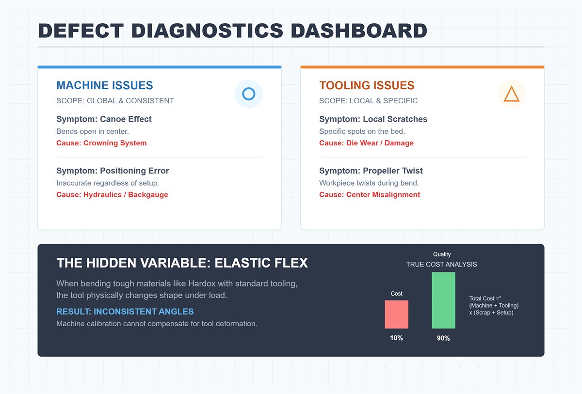
Machine-Related Issues: If the error is broad and consistent across the entire run, start by examining the machine. A textbook example is the “Canoe Effect,” where bends are correct at the ends but open in the center—signaling a problem with the crowning system that compensates for frame deflection. Similarly, if backgauge positioning loses accuracy regardless of the tooling setup, the root of the problem lies within the machine’s mechanical or hydraulic systems.
The Tooling Problem: When defects appear only in specific areas or on certain features, the tooling is often to blame. For example, if a scratch occurs exclusively with one particular die or if the bend angle shifts only at a precise spot along the bed, check for wear on the die’s shoulders or damage to its tip. Also verify the alignment between punch and die centers; even slight misalignment can cause the workpiece to twist in a “propeller” fashion—a distortion that cannot be corrected through machine settings alone.
The Hidden Variable: In many cases, what seems like a machine precision problem is actually a mismatch in material and tooling hardness. Attempting to bend tough, abrasive grades such as Hardox with standard 42CrMo tooling is a common mistake. Under extreme contact pressures, the tooling undergoes microscopic elastic flex—changing shape ever so slightly—making consistent angle control impossible. Even the most precise CNC calibration can’t compensate for a tool that is physically yielding under load.
Accurate cost assessment must go beyond the initial purchase price. The real equation factors in the machine cost plus tooling cost, multiplied by the scrap rate and setup time. While tooling might account for less than 10% of the upfront investment, it governs up to 90% of the finished product’s quality.
Contact us if you need help diagnosing tooling compatibility or selecting materials that match your fabrication requirements.
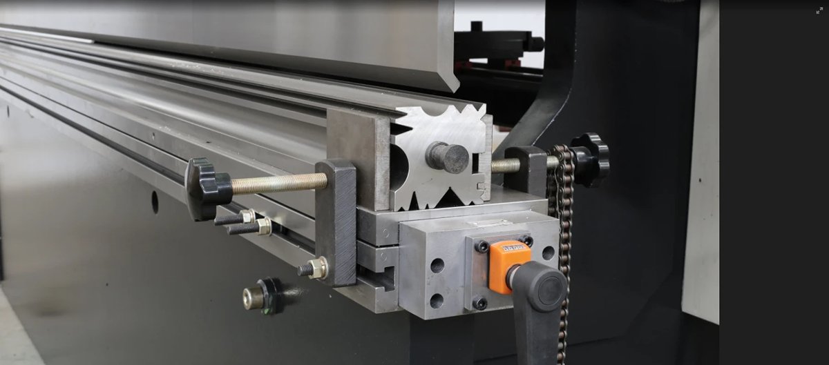
Many operators assume you need to track down original purchase documents or measure flange widths with precision calipers to determine your tooling system. In reality, this isn’t necessary. Identification relies on observing two key features: the “neck” (clamping tang) and the “shoulders” (load-bearing surfaces) of the tooling.
The connection between the tool and the machine’s ram governs everything from maximum tonnage to how quickly setup can be completed. By examining how the punch is held and how the force is transmitted, you can classify your tooling range almost instantly.
All the telltale signs are located in the upper section of the punch.
American Style: The Simple Tang
If the punch top is just a straightforward, rectangular block without complex shapes, you are looking at American Planer (Traditional) tooling.
European Style (Promecam): The Offset Hook — This design is the most common globally and can be easily identified by its distinctive asymmetrical profile.
Wila / New Standard (NS): The Safety Button — If a punch looks purpose-built rather than merely machined, it’s probably part of the New Standard system.
| Tooling Style | Key Visual Marker | Tang Dimensions & Features | Force Logic / Design | Clamping or Loading Mechanism | Additional Notes |
|---|---|---|---|---|---|
| American Style (Planer / Traditional) | Simple, rectangular tang with no complex shapes | Tang approx. 0.5 in (12.7 mm) wide; plain and upright projection | In-line force path — punch tip directly beneath tang center | Horizontal clamping bar with screws presses tang sideways | Alignment can vary between setups |
| European Style (Promecam) | Offset hook profile; asymmetrical shape | Slim tang (~13 mm) with safety groove or hook on one side | Offset design — punch tip shifted back for deeper bends | Uses offset configuration to prevent interference with clamping assembly | Z1 vs. Z2 offset (≈7 mm) must match to avoid bend misalignment |
| Wila / New Standard (NS) | Centrally located spring-loaded safety button | Wide tang (~20 mm) with integrated button or pin | Purpose-built, precise alignment design | Vertical Tool Loading — lift punch into place, button locks before clamp engages | Designed for convenience and safety; common in modern setups |
“New Standard” is not just a marketing phrase from Wila or Trumpf; it denotes a precisely defined engineering specification created to overcome the limitations of traditional American and European systems. Its purpose is to eliminate the “setup gap” — the wasted time spent fine-tuning tools that should already be perfectly aligned.
At the heart of the New Standard system is Self-Seating technology. In conventional American setups, tightening the clamp can slightly tilt the punch. In contrast, the New Standard’s hydraulic or pneumatic mechanism actively pulls the tool up into the holder during clamping, ensuring consistent, precise seating against the load-bearing surface and guaranteeing accurate vertical alignment every time.
In addition, the New Standard places a strong emphasis on Tx/Ty Axial Accuracy. Both the working height (Ty) and the centerline position (Tx) are maintained within micron-level tolerances. This level of precision allows operators to replace a worn tool with a brand-new one, or to combine segmented tools from different production batches, without having to reconfigure the machine’s backgauge or adjust depth settings.
In an effort to avoid purchasing entirely new tooling, many fabrication shops turn to adapters to connect mismatched systems—such as fitting European tools into American machines, or the reverse. While this can be made to work physically, it introduces three subtle yet serious threats to both precision and safety.
1. The Adapter Penalty (Tonnage Derating)
The capacity of a tooling setup is dictated by its weakest component. You might operate a 200-ton press brake with a punch rated for 150 tons per meter, but if the adapter between them is only rated for 100 tons per meter, that lower figure becomes your operational limit. Many operators fail to account for the adapter’s load rating, which can result in permanent deformation or sudden, catastrophic failure under pressure.
2. Stack-up Error
Achieving precision means minimizing points of variance. A typical configuration involves a single connection: Machine → Tool. Introducing an adapter adds an extra interface: Machine → Adapter → Tool. If the adapter has a tolerance of ±0.02 mm and the tool ±0.01 mm, these inaccuracies add together rather than cancel out. This cumulative “stack-up” can cause angular distortions that even advanced crowning systems struggle to correct—especially critical in high-precision fields like aerospace or medical manufacturing.
3. Torsional Force and Machine Damage
This is the most financially devastating long-term consequence. European tool designs are offset, meaning the load is positioned away from the center, while American press brakes are engineered for in-line forces directly down the center. Mounting an offset European tool on an American machine via an adapter generates torque—a twisting motion—instead of a pure vertical load. Over time, this torsional stress causes uneven wear to the ram guides and gibs, permanently reducing the machine’s alignment accuracy.
Determining your system type takes just minutes, but repairing the damage caused by improper tool mixing can take weeks. If adapters are unavoidable, always lower your tonnage limits accordingly and check the setup for any drift from the centerline.
Tonnage is the most critical—and potentially most dangerous—factor in press brake operations. An incorrect choice of tooling may lead to faulty parts, but errors in tonnage calculation can cause total equipment failure. This isn’t just about snapping a $2,000 punch; it’s about the very real possibility of permanently compromising the structural integrity of a machine worth hundreds of thousands of dollars.
Many operators work under a dangerously flawed assumption: “If the total force required is below the machine’s rated capacity, I’m safe.” In reality, this misunderstanding can be financially devastating. Protecting your equipment means thinking beyond total tonnage—you must understand how the load is distributed across the machine.
The “100 Tons” displayed on a machine’s nameplate reflects the full output capability of its hydraulic system—it does not indicate the maximum structural strength of the frame at one specific location. Safe operation demands mastery of two separate calculations: Distributed Load Capacity and Tooling Point Load.
Distributed Load Capacity describes how much force the machine can withstand when spread evenly along its entire length. Press brakes are generally engineered to handle a full-length distributed load. For instance, a 10-foot (3-meter) brake rated at 100 tons offers a structural limit of 10 tons per foot (approximately 33 tons per meter).
Here’s the hidden danger: If you concentrate 50 tons of force into a single 1-foot segment at the bed’s center, the hydraulics will effortlessly supply that force—since 50 tons is well under the 100-ton hydraulic capacity. Yet you’ve actually imposed five times the structural limit (10 tons per foot) on that specific section of the ram and bed. Hydraulic pressure may hold, but the steel frame might fail catastrophically.
Tooling Point Load is the other critical threshold. Just as machines have structural limits, every punch and die has a breaking point. Premium tooling manufacturers—like Wila or Trumpf—specify a “Max Load” in their catalogs, typically stated in tons per meter or per foot.
Consider this example: You’re working with a 4-inch (100 mm) tooling segment, and your calculations show the bend will require 20 tons of force.
Using short tooling segments to bend thick plate is one of the most common causes of lasting press brake damage. This practice creates a “Danger Zone” where extreme force concentration surpasses the yield strength of critical machine components.
When you opt for a short tool segment—say, 20mm or 1 inch wide—the immense pressure from the hydraulic cylinders cannot disperse effectively through the tool shoulder into the ram. It’s like the difference between wearing sneakers versus stiletto heels on soft ground: the stiletto sinks because the load is focused on a tiny contact area.
Exceeding the “tons per foot” limit at the machine’s center causes Ram Upset—where the ram’s steel (the upper moving beam) is compressed beyond its elastic range and permanently deforms.
Additionally, be alert to Sink Tonnage. In bottoming or coining, the tooling effectively tries to cut into the die holder. On narrow rail systems, the limited contact area drives pressure into grooves in the holder. If your inspection reveals depressions in the lower holder, inconsistent bending angles are probably due to the die “sinking” into these divots—not a miscalibration of the machine.
Think of a press brake’s “Max Capacity” like the redline on a car’s tachometer—it marks the danger zone, not the standard operating speed. Treating it as your everyday target is a recipe for premature failure.
For long-term reliability, follow the 60% Rule when centerline loading. If bending short parts in the middle of the machine, never exceed 60% of its total rated tonnage—regardless of what the hydraulics are technically capable of. When full tonnage is unavoidable, use tooling that spans most of the bed to evenly distribute the stress.
Always factor in the fatigue life of your press brake. Operating at peak capacity day after day accelerates wear on hydraulic seals, valves, and even the machine’s frame due to repeated stress cycles. If your regular workload demands 90 tons of force, relying on a 100-ton press brake is pushing it to the limit. Instead, opt for a 150-ton model so that routine tasks fall well within a safe, sustainable load range.
Quick Win: The Die Holder Inspection
Head over to your press brake and run your fingers along the top surface of the lower die holder—the flat area where the die rests. Do you notice any ridges, dips, or grooves?
In metal fabrication, many believe a truly versatile shop must own an extensive collection of highly specialized dies to tackle every possible profile. In reality, this approach is costly and misguided. The most profitable press brake operations don’t own the most tools—they own the right tools and know how to use them to their fullest potential.
A streamlined tooling library isn’t about amassing steel; it’s about ensuring every investment in hardened tooling generates a tangible return in production. The difference between a well-curated, productive library and a “graveyard”—rows of neglected, rusted dies—is recognizing which tools are truly indispensable and which are niche indulgences.
To explore the most efficient tooling line-ups, download our latest Brochures.
Press brake tooling follows the Pareto Principle closely: 80% of fabrication is accomplished with just 20% of tool profiles. Too many shops fall into the trap of buying highly specialized dies for hypothetical scenarios, tying up capital that could be invested in superior quality versions of core tools.
To build a lean, high-performance tooling library, start with this essential lineup:
Two Sets of Full-Length Straight Punches: These are the backbone of everyday bending work. Having duplicate sets allows you to handle long bends or run multiple setups along the machine bed without having to dismantle and reset tooling.
One Set of Full-Length Gooseneck Punches: Think of this as the “master key” in the press brake toolbox. Thanks to its deep relief design, a gooseneck punch can form substantial U-channels and return bends—shapes that would clash with the contour of a standard straight punch. When clearance is a challenge, this profile offers unmatched versatility.
One Set of Segmented Punches with Horns: While fixed-length punches have their place, box bending demands a segmented setup. A kit that includes specialized “ear” or “horn” segments lets the operator form box sides without the tooling colliding with pre-bent flanges from earlier operations.
One Set of 30° Acute Dies: Although 90° dies dominate general use, a 30° acute die offers far greater adaptability. With controlled ram depth, you can air bend anything from 30° to 180°. It’s also essential for hemming—flattening edges as a preliminary step.
The Air Bending Advantage: Don’t fall into the trap of buying radius-specific dies for every blueprint that calls for a particular internal radius. In modern air bending, that radius is determined primarily by the V-die opening, not the punch tip radius. By adjusting the V-width and penetration depth, one tool set can produce a wide array of radii. Reserve dedicated radius tooling for parts you produce frequently—especially if precise “bottoming” is needed for a consistent, repeatable radius.
When deciding between American Planed and Precision Ground tooling, many hesitate over the price difference. But in this case, a lower upfront cost doesn’t necessarily translate to better value over time. Your choice should hinge on the precision requirements and production flow in your facility.
American Planed Tooling: Crafted using a planing method—much like shaving layers off wood—this manufacturing approach yields a functional yet less refined product.
Precision Ground Tooling: These tools are finished using CNC grinding machines that reference every critical dimension—tang, shoulder, and tip—from a single central axis, ensuring perfect geometric alignment.
Tooling improvements should be considered essential performance features, not optional luxuries. The choice to invest in advanced hardening or coatings should be based strictly on the materials being formed and the demands of each job.
Laser Hardening: Conventional flame hardening often produces uneven results. In contrast, premium tooling brands—such as Wila or Wilson Tool—employ laser hardening. This method rapidly heats the tool’s working zones (the tip and load-bearing shoulders), creating a self-quenching effect that hardens up to 4mm deep at 60 HRC. Just as importantly, the tool’s core remains tough and ductile, preventing fractures under load while keeping wear surfaces exceptionally durable.
Nitride / TiCN Coatings for Galvanized Steel: When fabricating large volumes of galvanized steel, standard tooling quickly deteriorates. The zinc layer on the sheet behaves almost like a soft wax—under high bending pressure, it shears off and adheres to the die. This reaction, known as galling, leaves the tool surface rough and scars every subsequent piece bent with it.
Heavy-Duty Coatings for High-Strength Steel: When bending stainless or other high-tensile materials, abrasive wear becomes the primary challenge. Even laser-hardened tooling can degrade under the extreme contact forces required for metals like Hardox or Domex. In these demanding conditions, robust wear-resistant coatings are essential to preserve the tool tip’s integrity and maintain its precise radius over extended use.
Before committing to a purchase, ask yourself the key question: “Is this tool for a single project, or will it handle over a million cycles?” If it’s the latter, investing in the highest-grade, precision-ground, coated option is almost always the most cost-effective choice over the long run—measured on a per-bend basis.
Tool maintenance is often mistakenly viewed as a simple clean-and-store task. In reality, it’s a critical safeguard for your most valuable asset—precision. High-quality tooling rarely fails in a dramatic fashion; instead, it deteriorates gradually, much like a chronic condition, quietly increasing setup times and driving up scrap rates.
Preventive practices and protective coatings, such as those offered for Shear Blades and Laser Accessories, can extend service life and reduce maintenance frequency.
The real risk lies in how inconspicuous wear can be. A punch or die that appears serviceable might already be out of spec in subtle but important ways. Recognizing the signs of tool wear enables you to stop chasing machine adjustments and focus on the actual root cause—the interactions between the metal and the sheet during forming.
One of the most frequent diagnostic mistakes in press brake operations occurs with long bends. Picture an operator forming a 10-foot (3-meter) panel: while the ends measure a perfect 90 degrees, the middle opens up to 92 degrees, producing a slight bow in the center that mimics the shape of a canoe hull.
The instinctive reaction is to blame the press brake, suspecting the crowning—or deflection compensation—system is out of calibration. The operator may increase crowning to correct the center, which can achieve a 90-degree bend there but will over-bend the ends. This is a classic case of chasing a non-existent problem.
The real culprit is often hidden in the V-die shoulders. Because operators habitually position smaller parts in the exact middle of the press brake, that central section of the die endures far more bends than the ends. Over time, repeated contact gradually wears down the shoulder radius in the center.
Although a worn shoulder might seem trivial at first glance, the mechanical consequences are significant. A larger, worn radius generates less friction than the sharper, original edges at the die’s ends. This means the material slides into the cavity more easily and at a faster rate in the middle. Even a slight increase—just 0.004 inch (0.1 mm)—in the V-opening width alters the effective V-size, changing how deep the punch must penetrate to achieve the desired angle.
To verify this, avoid making adjustments to the CNC controller. Instead, lay a precision straight edge along the V-die shoulder and view it against a light source. If you spot light seeping through in the center, or feel a noticeable groove with your fingernail, you’ve found the problem. Hydraulic crowning adjustments cannot compensate for a die that’s lost its original geometry.
Once a tool is confirmed worn, the instinctive move is to send it out for regrinding. On paper, paying a few hundred dollars to resurface it sounds far better than spending several thousand for a new precision-ground tool. However, that apparent saving often becomes an expensive misstep.
The chief problem is losing shut height uniformity. In manufacturing, precision tooling is built to exact height tolerances so segments can be freely combined. Regrinding removes material and changes the tool’s overall height. If your shop ends up with a mix of “factory height” and “reground height” tools, and an operator unknowingly uses both in one setup, you’ll see severe angle variations along the bend line.
To counter this mismatch, operators resort to shimming—placing thin sheets of paper or metal beneath the die to level it. This is where the supposed savings disappear. Regrinding might shave $500 off the immediate cost, but if the operator spends half an hour shimming the tool every time it’s installed, labor quickly outweighs the initial saving. At typical machine-hour rates, just a few weeks of working around inconsistent tool heights can cost more than purchasing a brand-new die.
There’s also a metallurgical penalty to consider. Most precision tools have a laser-hardened surface layer just 3–4 mm deep—this is the protective “armor” that gives the tool its hardness and wear resistance. When a tool is reground too aggressively, this layer can be completely removed, leaving the softer core steel exposed. Once that happens, the tool’s service life can shrink to just a fraction—often around 20%—of its original lifespan, forcing premature replacement. Unless you can confirm that the entire tool set has been reground together and re-hardened—a process that’s both rare and costly—purchasing a new tool is almost always the wiser, more economical choice.
You can often gauge a shop’s scrap rate just by glancing at its tooling rack. If punches and dies are piled horizontally like pieces of firewood, that’s a clear sign the shop is unknowingly eroding its own precision.
Precision-ground tools are hardened to roughly 60 HRC. This makes them exceptionally strong under compression but also brittle—much like glass. When hardened surfaces strike each other during stacking, micro-chipping occurs. These tiny fractures at the punch tip or die shoulder are often invisible, yet they imprint subtle, permanent flaws on every part that passes through them.
Impact isn’t the only risk. Stacked tools trap moisture and cutting fluids in the gaps between surfaces, creating “dead zones” where corrosion begins. The resulting rust doesn’t just mar appearance—it distorts mounting surfaces, prevents full seating in the holder, and introduces angle errors before the machine even makes its first stroke.
The only proper way to store precision tooling is to keep every piece isolated. Tools should be arranged so what you see on the rack is exactly what’s available—organized, protected, and ready for use:
The lifespan of your tooling isn’t defined by calendar years—it’s measured by the number of precise bends it delivers. Neglect a high-end Wila or Trumpf tool and it can turn into scrap metal in mere months. Treat it with the care reserved for precision instruments, however, and it can maintain exacting tolerances for decades.
Running a press brake tooling library is much like managing a financial portfolio: you need to weed out the underperformers to safeguard your top assets. If your tooling rack resembles a jumble-sale collection, you’re almost certainly losing profits through excessive scrap and sluggish setup times. An audit goes far beyond counting pieces—it’s about confirming capability and readiness. For shops with mixed equipment, integrating adaptable solutions like Punching & Ironworker Tools can enhance flexibility in production.
Don’t just note what’s on the shelf—conduct a full diagnostic. Remove every punch and die from the rack and subject them to both hands-on examination and data analysis.
Physical “Autopsy” Start with geometry: position a precision straightedge along the shoulders of your V-dies and the tips of your punches, then hold them to the light. Uneven gaps or visible scoring reveal tools that are causing angle inconsistencies—set them aside immediately. Then review the load history: check the back and sides for micro-cracks or distortion. Any tool with a hairline fracture isn’t an asset—it’s a hazard. Scrap it without hesitation. Lastly, watch for “orphans”: segmented sets mismatched in brand or height prevent consistent air bending. Assign these to non-critical jobs or remove them altogether.
Production Mix Reality Check Once you’ve confirmed tool condition, compare your inventory to ERP production data. Apply the 80/20 principle—focus on the ten material thicknesses that generate 80% of your revenue. Ensure you have the correct, dedicated V-openings for these gauges, typically 8x or 10x the material thickness.
Far too many shops make do with a V16 die for 1mm sheets because the proper V8 is missing—compromising quality. Likewise, running that same V16 on 3mm plate, when a V24 is needed, shortens the tool’s life dramatically. If a specialty tool hasn’t been used in over a year, move it to long-term storage. Reserve prime rack space for the tools that actively drive profits.
If your shop floor looks like a scrapyard of incompatible interfaces—American, European, and Promecam setups scattered across various machines—you’re dealing with poor utilization. The solution isn’t to replace your equipment, but to implement a smart “stop-loss” strategy that consolidates and streamlines your tooling approach.
The Adapter Strategy
Choose a forward-compatible interface standard, such as Wila New Standard or high-precision European style. Rather than buying machine-specific tools for aging equipment, invest in robust, precision-engineered adapters. These let you fit modern tooling onto older beams, freeing your tools from being tied to “that old press in the corner.” Suddenly, every tool in your collection can work across your entire shop, instantly boosting your effective utilization rate.
Visual Management and Shadow Boards
Standardizing tools also means removing operator uncertainty. Your team shouldn’t have to peer closely to tell an 88° punch from a 90°. Use strict color coding: apply a blue stripe for 88° tools, yellow for 90°, and red for 30°. This instantly conveys the tool’s specifications at a glance.
Pair this with shadow boards on your storage racks. Outline the shape of each tool in its assigned position. If the tool isn’t in the press and isn’t in its shadow, it’s officially missing. This easy visual check can eliminate the typical 30 minutes per shift spent searching for “that one gooseneck punch.”
The Weekend Action Plan
This weekend, keep the machines off. Instead, walk through your floor armed with a straightedge, a marker, and this checklist. You’ll probably discover that much of your “asset portfolio” is actually dragging you down—but recognizing those liabilities is the first step to stopping the losses.
 العربية
 বাংলা
বাংলা
 Български
 Čeština
 Dansk
Dansk
 Nederlands
 Suomi
Suomi
 Français
 Deutsch
 Ελληνικά
 עִבְרִית
 हिन्दी
 Magyar
 Bahasa Indonesia
 Italiano
 日本語
日本語
 Қазақ тілі
 한국어
한국어
 Bahasa Melayu
 Norsk bokmål
 فارسی
فارسی
 Polski
 Português
 Română
 Русский
 Српски језик
 Slovenčina
 Español de México
 Español
 Kiswahili
 Svenska
 Tagalog
 தமிழ்
தமிழ்
 ไทย
ไทย
 Türkçe
 Українська
 اردو
اردو
 Tiếng Việt
 简体中文
简体中文
 香港中文
香港中文
 繁體中文
繁體中文
